Liquid-liquid extraction unit, multistage liquid-liquid extraction apparatus using the unit, and multistage continuous extraction system for rare earth elements

a multi-stage liquid-liquid extraction and rare earth element technology, which is applied in the field of liquid-liquid extraction units, multi-stage liquid-liquid extraction apparatuses using the unit, and multi-stage continuous extraction systems for rare earth elements, can solve the problems of mixer-settler, loss of processing efficiency, and reaction cannot catch up at a high flow rate equivalent to the flow rate available, so as to achieve sufficient extraction efficiency and reduce the footprint , the effect of small siz

Inactive Publication Date: 2013-07-18
SHIN ETSU CHEM IND CO LTD
View PDF2 Cites 10 Cited by
  • Summary
  • Abstract
  • Description
  • Claims
  • Application Information

AI Technical Summary

Benefits of technology

[0041]The liquid-liquid extraction unit of the invention is of small size and maintains a sufficient extraction efficiency. When a multistage extraction apparatus comprising a plurality of units connected for fluid communication and a multistage continuous extraction system in which a plurality of sections each comprising the multistage extraction apparatus and assigned to different steps are connected for fluid communication are constructed, the footprint can be significantly reduced, and the volume of liquid necessary for extraction can be significantly reduced. These contribute to a substantial reduction of cost required for extraction and separation of rare earth elements.

Problems solved by technology

However, in the prior art method wherein aqueous and organic phases are contacted and separated solely via vertical upward and downward movements using a well-known spray column or a vertical cylindrical tank used in an extraction unit based on emulsion flow as described in Patent Document 4, reaction cannot catch up at a high flow rate equivalent to the flow rate available in the above-mentioned mixer-settler.
Thus reaction must be carried out at a low flow rate in order to maintain an acceptable efficiency, resulting in a loss of processing efficiency.

Method used


Image

  • Liquid-liquid extraction unit, multistage liquid-liquid extraction apparatus using the unit, and multistage continuous extraction system for rare earth elements
  • Liquid-liquid extraction unit, multistage liquid-liquid extraction apparatus using the unit, and multistage continuous extraction system for rare earth elements
  • Liquid-liquid extraction unit, multistage liquid-liquid extraction apparatus using the unit, and multistage continuous extraction system for rare earth elements

Examples


example

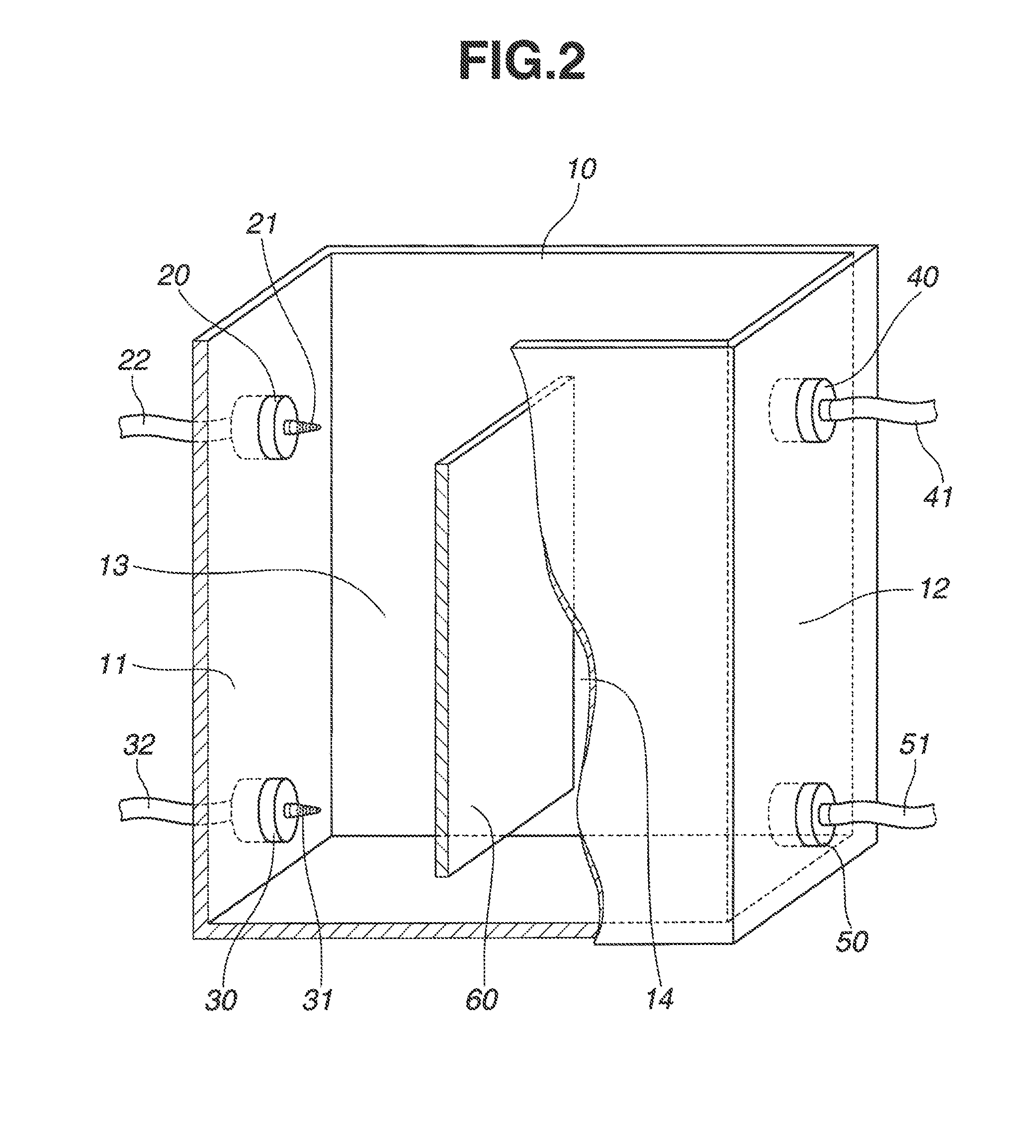
[0068]A multistage continuous extraction system was constructed as shown in FIG. 4. The system construction was the same as in FIG. 5 in Comparative Example except that extraction section A and scrubber section B were constructed using the liquid-liquid extraction units as shown in FIG. 2, and an alkali mixing section D for mixing a sodium hydroxide aqueous solution 3 with the organic phase 2 was disposed upstream of extraction section A. The back-extraction section C of 8 stages was constructed using a mixer-settler as in Comparative Example. The alkali mixing section D is a vessel dimensioned 80 mm×80 mm×200 mm and equipped with an impeller where the sodium hydroxide aqueous solution from line 3 is uniformly mixed with the organic phase 2 before the liquid is discharged or fed to extraction section A.

[0069]The liquid-liquid extraction unit shown in FIG. 2 is dimensioned 120 mm (W)×80 mm (D)×200 mm (H). A partition 60 of 5 mm×80 mm×170 mm (H) is disposed at a distance of 60 mm from...


PUM

PropertyMeasurementUnit
volumeaaaaaaaaaa
flow rateaaaaaaaaaa
flow rateaaaaaaaaaa

Abstract

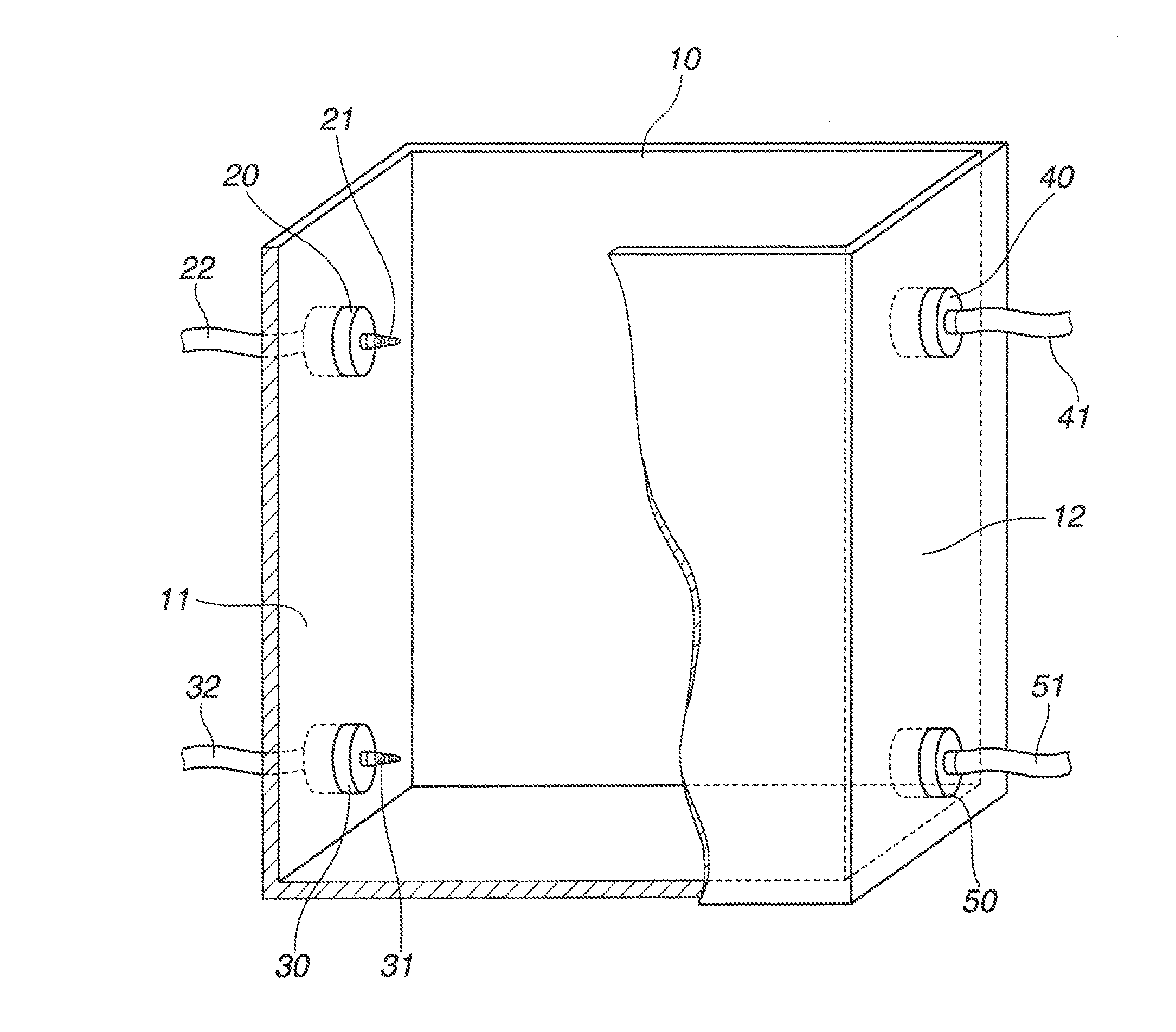
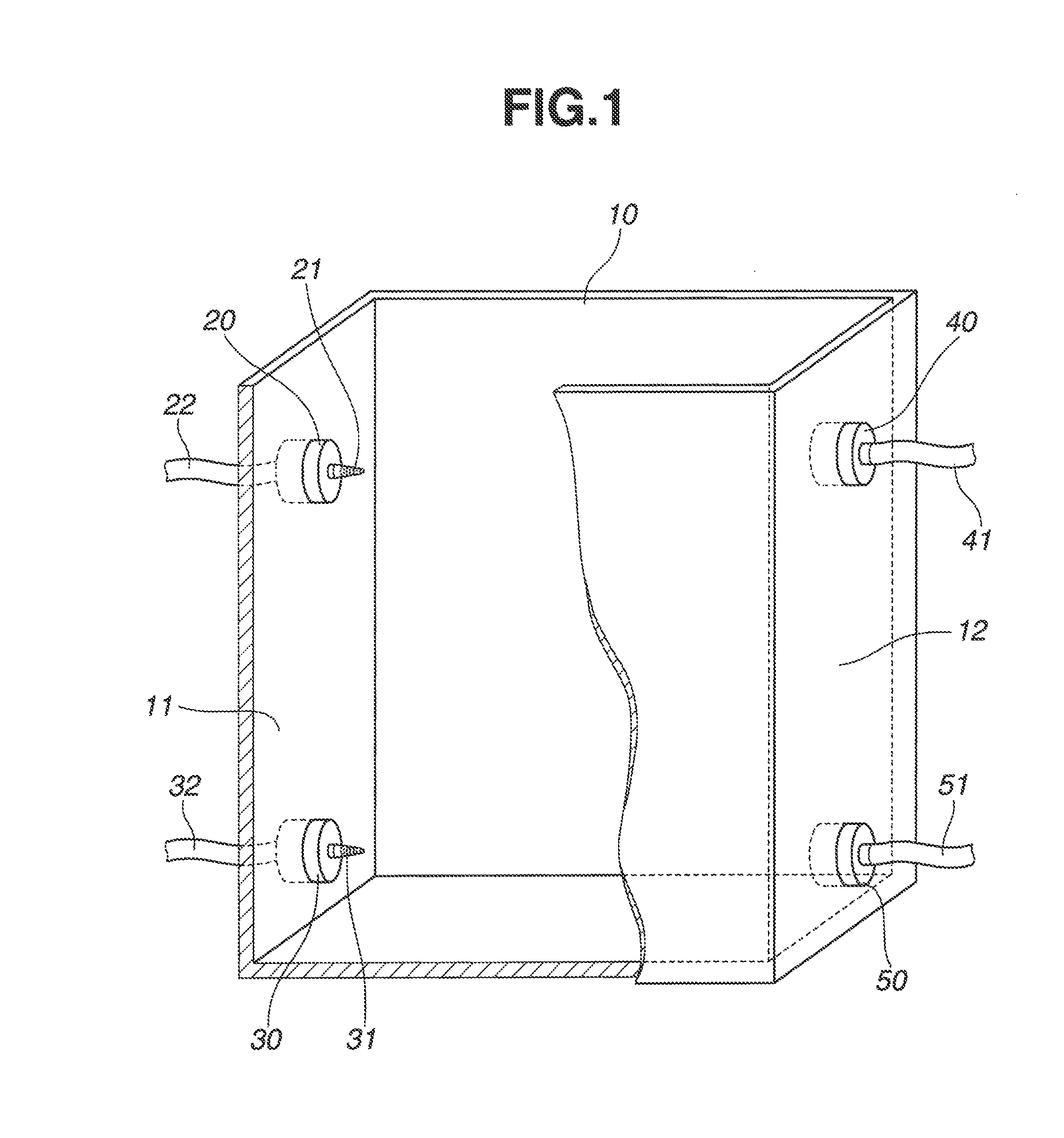
A liquid-liquid extraction unit includes an extraction/separation tank (10) into which an aqueous phase in bubble form is admitted from an upper inlet (20) in one sidewall and an organic phase in bubble form is admitted from a lower inlet (30) in the one sidewall. The upward moving organic phase is contacted with the downward moving aqueous phase. After contact, the organic phase is discharged through an upper outlet (40) in an opposite sidewall and the aqueous phase is discharged through a lower outlet (50) in the opposite sidewall.

Description

CROSS-REFERENCE TO RELATED APPLICATION[0001]This non-provisional application claims priority under 35 U.S.C. §119(a) on Patent Application No. 2012-005224 filed in Japan on Jan. 13, 2012, the entire contents of which are hereby incorporated by reference.TECHNICAL FIELD[0002]This invention relates to a liquid-liquid extraction unit adapted to contact an aqueous phase with an organic phase, separate them, and recover the desired extract from the thus separated aqueous phase and / or organic phase, more particularly, to a liquid-liquid extraction unit suitable for the extraction and separation of rare earth elements, especially rare earth elements including yttrium and light rare earth elements (La, Ce, Pr, Nd, Sm, and Eu); a multistage liquid-liquid extraction apparatus and a multistage continuous extraction system using the unit.BACKGROUND ART[0003]Nowadays, rare earth magnets as typified by Nd magnets are widely used in motors, sensors and other parts built in hard disk drives, air co...

Claims


Application Information

Patent Timeline
Patent Type & Authority Applications(United States)
IPC IPC(8): B01D11/04
CPCB01D11/0449C22B59/00C22B3/0005B01D11/04Y02E60/36Y02P10/20C22B3/26A45D44/00A61N1/44A61H9/0028A61H9/005C25B1/04A45D2200/202B01D2011/002
Inventor SUGAHARA, HIROTOMINOWA, TAKEHISA
Owner SHIN ETSU CHEM IND CO LTD
Why Eureka
Try Eureka