Robot controller, robot system, robot control method

a robot controller and robot technology, applied in the direction of programmed manipulators, programme control, instruments, etc., can solve the problems of large movement, virtual displacement, large movement, etc., and achieve the effect of facilitating verification of the stability of the solution

Active Publication Date: 2013-07-18
SEIKO EPSON CORP
View PDF14 Cites 34 Cited by
  • Summary
  • Abstract
  • Description
  • Claims
  • Application Information

AI Technical Summary

Benefits of technology

[0016]An advantage of some aspects of the invention is to provide a robot controller, a robot system, and a robot control method that perform nonlinear impedance control and facilitate verification of stability of the solution of the equation of motion and realization as hardware.
[0018]In the aspect of the invention, by performing filter processing on the output value of the linear impedance processing, nonlinear impedance control may be realized. Further, by using the combination of linear systems, the stability of the solution of the equation of motion can be verified.
[0020]In this aspect of the invention, by performing filter processing on the input value of the linear impedance processing, nonlinear impedance control may be realized. Further, by using the combination of linear systems, the stability of the solution of the equation of motion can be verified.

Problems solved by technology

However, in the case where large force is necessary, if large virtual displacement is specified, when external force for the force disappears, the manipulator produces very large movement corresponding to the specified virtual displacement.
Such large movement is very problematic in practice and safety.
Further, by specifying large virtual displacement, large force (external force) can be produced in principle, however, there is a problem that a workpiece as an object of operation of the robot may be broken by the produced force.
These are the problems caused by impedance control for linear output with respect to virtual displacement.
However, in this technology, there is a problem that it is very difficult to determine whether or not the equation of motion used for force control is stable.
However, in this technology, it is difficult to design the sliding mode control system, and the technology is not suitable for practical use.

Method used


Image

  • Robot controller, robot system, robot control method
  • Robot controller, robot system, robot control method
  • Robot controller, robot system, robot control method

Examples


first embodiment

2. First Embodiment

2.1 Configuration

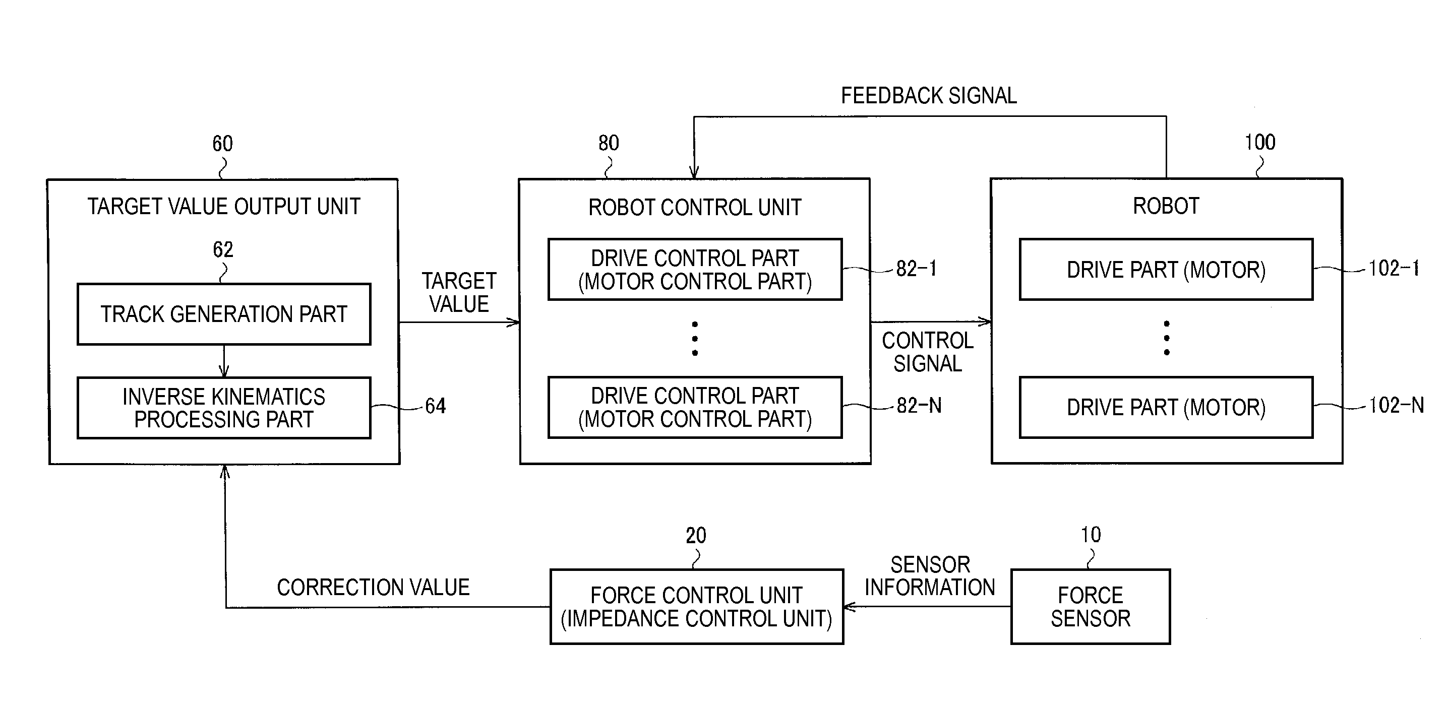
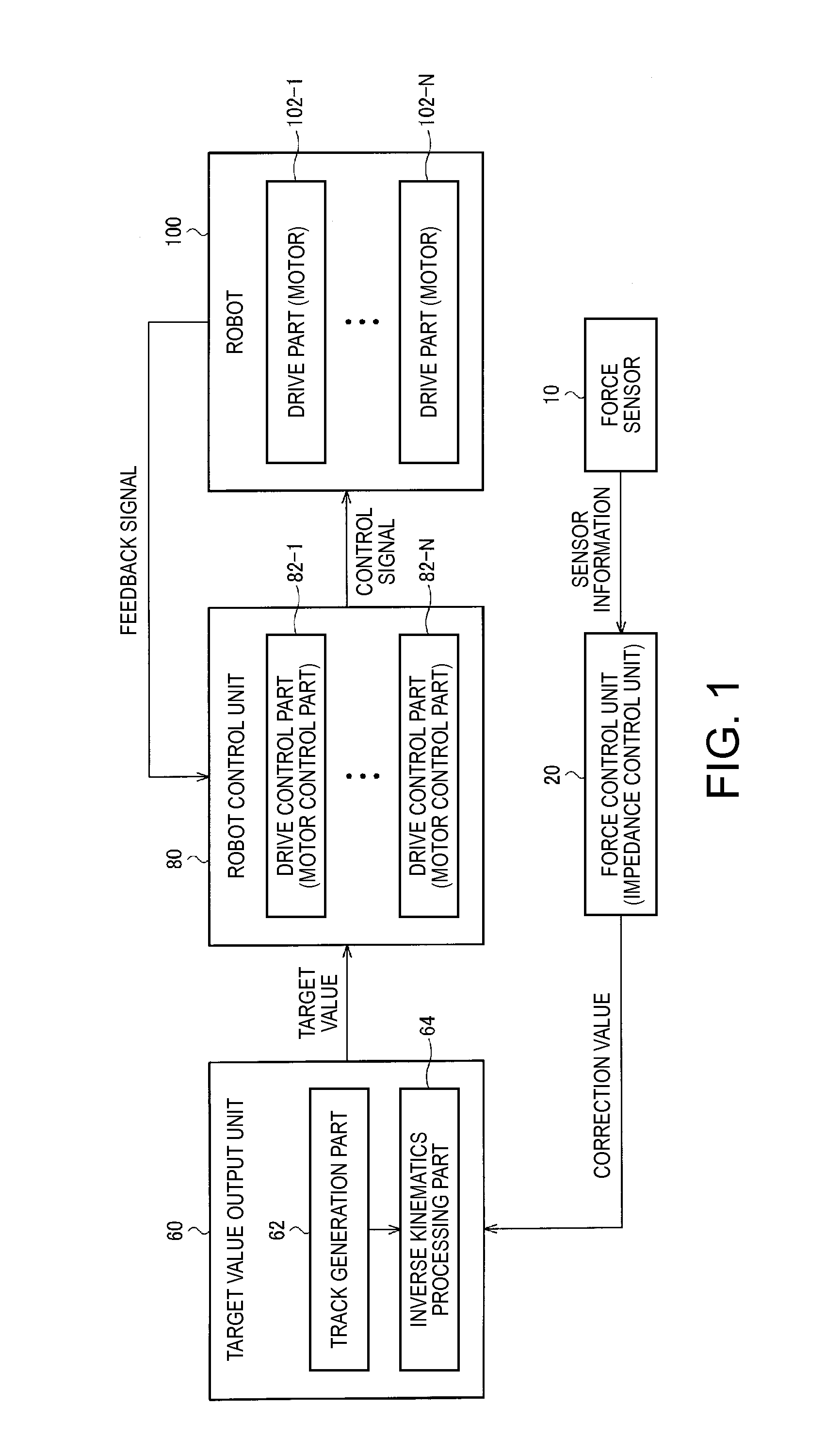
[0124]FIG. 13 shows a configuration example of a robot controller according to the first embodiment.

[0125]The force sensor 10, the target value output unit 60 (the track generation part 62 and the inverse kinematics processor 64), the robot control unit 80 (the motor control part 82-1 to the motor control part 82-N) are the same as those in FIG. 1, and their detailed explanation will be omitted. Further, an input correction unit 30 performs correction processing on the detected sensor value (sensor information), and may include the position correction part 532, the hand and tool self-weight correction part 534 of FIG. 8, for example. A forward kinematics processing unit 40 corresponds to the forward kinematics processor 540 in FIG. 8, and outputs a result of forward kinematics processing to the input correction unit 30, and the unit may output the result to the track generation part 62 as desired.

[0126]Further, the force control unit 20 of the rob...

second embodiment

3. Second Embodiment

3.1 Configuration

[0176]FIG. 19 shows a configuration example of a robot controller according to the second embodiment.

[0177]The force sensor 10, the input correction unit 30, the forward kinematics processing unit 40, the target value output unit 60 (the track generation part 62 and the inverse kinematics processor 64), the robot control unit 80 (the motor control part 82-1 to the motor control part 82-N), are the same as those of the first embodiment shown in FIG. 13, and their detailed explanation will be omitted.

[0178]Further, like FIG. 13, the force control unit 20 of the robot controller includes an impedance processor 21, a control parameter memory part 24, and a nonlinear convertor 29. Note that the controller is different from that of the first embodiment in that the impedance processor 21 and the nonlinear convertor 29 are oppositely arranged.

[0179]Accordingly, the nonlinear convertor 29 performs filter processing on an external value I acquired from the...


PUM


Abstract

A robot controller includes a force control unit that outputs a correction value of a target track of a robot based on a detected sensor value acquired from a force sensor, a target value output unit that obtains a target value by performing correction processing on the target track based on the correction value and outputs the obtained target value, and a robot control unit that performs feedback control of the robot based on the target value. The force control unit includes an impedance processor that obtains a solution of a differential equation in force control as the correction value before the conversion processing, and a nonlinear convertor that obtains the correction value after the conversion processing by performing nonlinear conversion processing on the correction value before the conversion processing acquired from the impedance processor and outputs the obtained correction value after the conversion processing.

Description

BACKGROUND[0001]1. Technical Field[0002]The present invention relates to a robot controller, a robot system, and a robot control method.[0003]2. Related Art[0004]Operations using robots such as manipulators include operations with various constraints, for example, in contact with objects. In these cases, force control is often required in addition to location control. For example, in the cases of tracing the surface of an object, fitting one object in another object, and grasping a soft object so as not to break it, movement in response to the reaction force from the object is necessary in addition to simple location control.[0005]Representative methods of force control in robots include a method called impedance control. Impedance control is a control method of moving a robot, regardless of its real mass, viscosity property, and elasticity property, as if it had those values suitable for an operation. This is a control method of solving an equation of motion based on force informat...

Claims


Application Information

Patent Timeline
Patent Type & Authority Applications(United States)
IPC IPC(8): G05B19/408G06F17/13
CPCB25J9/1633B25J9/1648G05B2219/39343G05B2219/41124Y10S901/02G05B2219/42267G05B19/4086G06F17/13G05B2219/42092Y10S901/09B25J9/1605B25J9/1664B25J9/1694
Inventor INAZUMI, MITSUHIRO
Owner SEIKO EPSON CORP
Why Eureka
Try Eureka