Method and apparatus for milling of railroad track

a technology for railroad tracks and milling plates, applied in shaping cutters, manufacturing tools, ways, etc., can solve problems such as cracks, deformations, irregularities, and deformations along the track surface, and achieve the effects of reducing downtime, improving the useful life of the milling plate, and easy removal and replacemen

Inactive Publication Date: 2013-07-25
LORAM MAINTENANCE OF WAY
View PDF11 Cites 18 Cited by
  • Summary
  • Abstract
  • Description
  • Claims
  • Application Information

AI Technical Summary

Benefits of technology

[0011]The present invention is directed to a railway milling system that can be pulled along sections of track and comprises a plurality of milling plates, each plate including a plurality of milling blades for engaging the track surface so as to remove irregularities from the track surface. The plurality of milling blades are generally arranged along the periphery of the milling plate. The milling blades can be oriented above a length of rail such that the milling blades contact and mill the rail in a perpendicular orientation to the rail along sections of track that lack encumbrances. Alternatively, the milling blades can be angled and oriented such that milling...

Problems solved by technology

Use of these tracks to support heavy loads travelling at high speeds results in the formation of irregularities such as pits, burrs, cracks and deformations along the track surface.
These irregularities can create excessive noise and vibrations as the wheels of the train car contact the irregularities.
Similarly, the irregularities can also increase the fatigue on the rails and the train cars themselves creating substantial safety and maintenance problems.
Although the irregularities can often be easily smoothed out of the track by grinding or milling the surface of each track section in a machine shop, removing each section for regular maintenance is impractical and expensive.
Because of factors including different load weights and configurations of the trains traveling over the rails or even installation factors such as, for example, differing soil conditions beneath the rails, the track surface can wear unevenly along the railway.
The drawback of the Type 1 configuration is that the large surface area of the abrasive surface for each rotating element creates a substantial amount of friction requiring a relatively powerful motor to rotate the rotating element.
While maximizing the effectiveness of the abrasive pad, the friction created by the grinding acts as a brake slowing the grinding process, which can lead to increased amounts of downtime for the rail line being grinded.
In this grinding configuration, the abrasive surface of an individual rotating element...

Method used


Image

  • Method and apparatus for milling of railroad track
  • Method and apparatus for milling of railroad track
  • Method and apparatus for milling of railroad track

Examples


Embodiment Construction

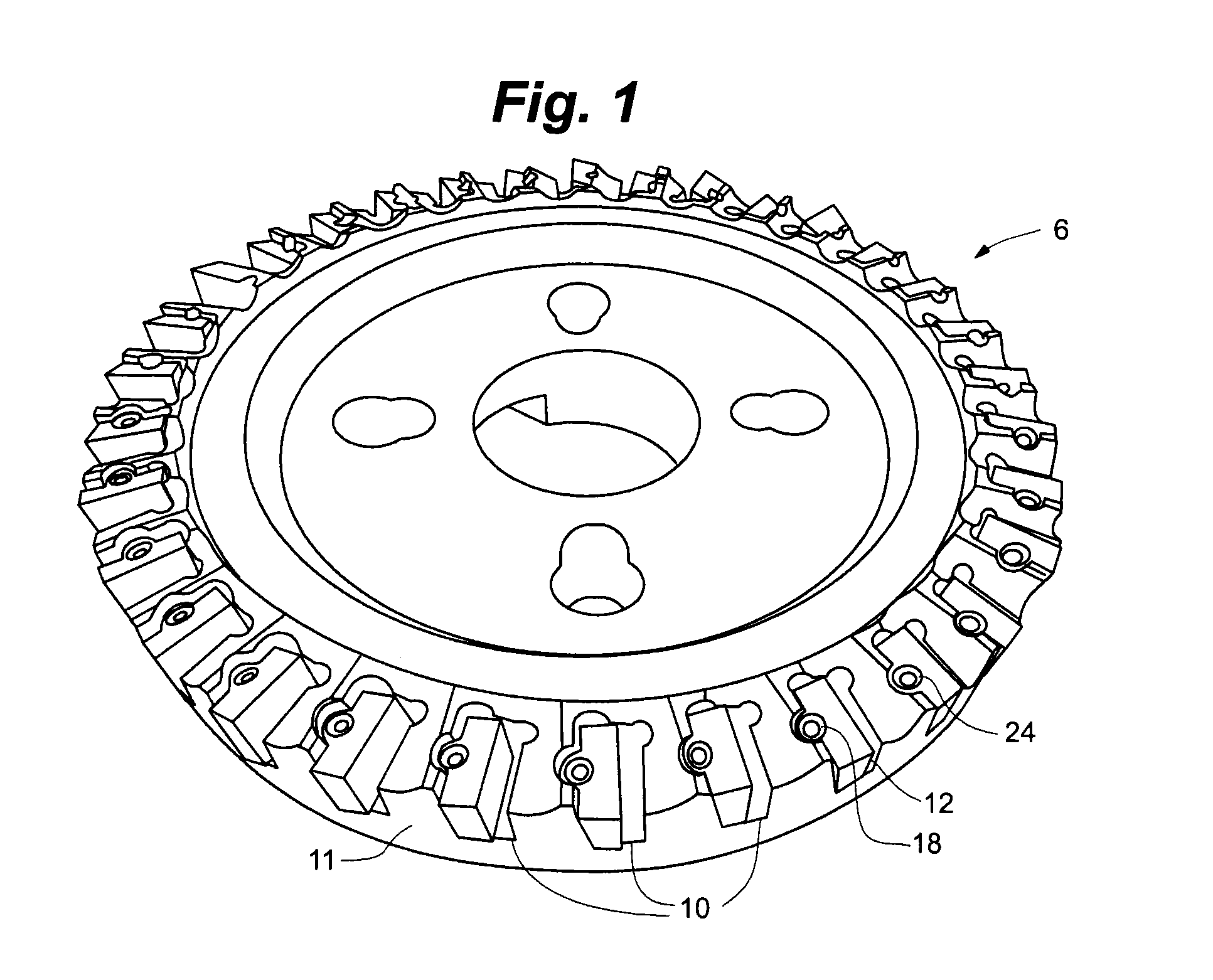
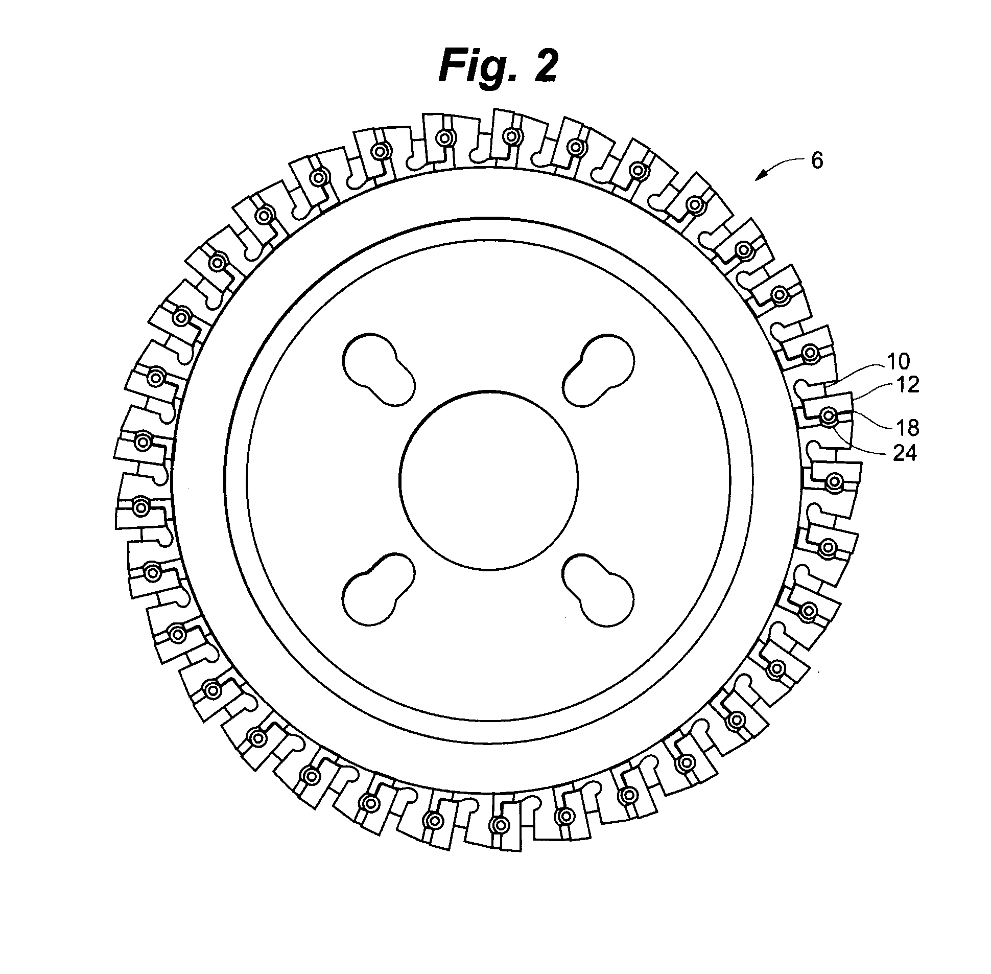
[0033]As illustrated in FIGS. 1 and 2, a representative embodiment of a milling plate 6 according to the present invention generally comprises a plurality of blade slots 10 each having a corresponding adjustable vice grip 12 and milling blade 14. The plurality of blade slots 10 are generally positioned proximate to a perimeter edge 11 of the plate 6 and each blade slot 10 further comprises a threaded slot bore (not shown) along one side of the slot 10. Each adjustable vice grip 12 further comprises a threaded vice bore 18 corresponding to the threaded slot bore of one of the plurality of slots 10. As shown in FIGS. 4 and 5, an embodiment of the milling blade 14 can comprise a generally rectangular shape having an angled milling surface 19 for milling the track surface

[0034]As shown in FIGS. 1-2, each milling blade 14 is insertable into a corresponding slot 10 and retained by the adjustable vice grip 12. The adjustable vice grip 12 further comprises a flat side 20 for aligning the vi...


PUM

PropertyMeasurementUnit
Depthaaaaaaaaaa
Heightaaaaaaaaaa
Perimeteraaaaaaaaaa

Abstract

A milling system for milling a track surface with at least one rotatable milling plate. A modular blade system for each milling plate allows individual blades to be removed and replaced when an individual blade becomes dull or broken. The blade system also allows the milling plates to be oriented in both Type 2 and Type 3 configurations depending upon track surroundings and the presence of encumbrance. The milling plates can be mounted to a positioning assembly for adjusting the relative distance between the milling plate and the track surface as well as the angle at which the milling plate engages the track surface. The milling system can include a depth guide so as to physically prevent the milling plate from cutting too deeply into the track surface.

Description

RELATED APPLICATION[0001]The present application claims the benefit of U.S. Provisional Application No. 61 / 588,472 filed Jan. 19, 2012, which is incorporated herein in its entirety by reference.FIELD OF THE DISCLOSURE[0002]The present invention relates generally to railway maintenance. More specifically, the present invention is directed to an apparatus and related methods for milling a track surface to remove irregularities in the track surface.BACKGROUND OF THE DISCLOSURE[0003]Railroad tracks generally comprise a pair of metal rails arranged in a parallel configuration so as to guide and support metal wheels of train cars. Use of these tracks to support heavy loads travelling at high speeds results in the formation of irregularities such as pits, burrs, cracks and deformations along the track surface. These irregularities can create excessive noise and vibrations as the wheels of the train car contact the irregularities. Similarly, the irregularities can also increase the fatigue ...

Claims


Application Information

Patent Timeline
IPC IPC(8): E01B31/13B23C3/00B23C5/20
CPCE01B31/13B23C5/20B23C3/005B23C5/2269Y10T409/306384Y10T409/303808Y10T407/192Y10T407/1908B23C2200/0455
Inventor BEHRENS, JON THOMAS
Owner LORAM MAINTENANCE OF WAY
Why Eureka
Try Eureka