Photoacoustic transducer and imaging system

a transducer and imaging system technology, applied in the field of photoacoustic imaging and medical diagnostics, can solve the problems of unsuitable for some applications, ultrasound waves do not pass through certain types of tissues, and limitations of conventional ultrasound technology

Inactive Publication Date: 2013-07-25
FUJIFILM SONOSITE
View PDF19 Cites 74 Cited by
  • Summary
  • Abstract
  • Description
  • Claims
  • Application Information

AI Technical Summary

Benefits of technology

[0009]Typically, the optical fibers in the housing are joined together to form a bundle or cable. This bundle or cable may further include one or more electrical wires to form a coaxial cable. The electrical wires of the coaxial cable run from the transducer located in the nosepiece of the scan head to a connector that interfaces with an ultrasound transceiver or beamformer. The optical fibers run from one or more positions adjacent to the transducer to a connector that interfaces with a laser system.
[0010]In certain implementations of the invention, the light-emitting end of the bundle of fibers may be divided into two or more groups of fibers that are positioned next to the transducer within the nosepiece of the housing. For example, the optical fibers may be arranged into two separate bundles with the light-emitting end of each ...

Problems solved by technology

However, conventional ultrasound technology has limitations that make it unsuitable for some applications.
For example, ultrasound waves do not pass well through certain types of tissues and anatomical features, and ultrasound images typically have poorer contrast than X-Ray and MRI images.
Also, ultrasonic imaging has difficulties distinguishing between acoustically homogenous tissues (i.e. tissues having similar ultrasonic properties).
Although well suited for a single round transducer, this approach is less suitable for a r...

Method used


Image

  • Photoacoustic transducer and imaging system
  • Photoacoustic transducer and imaging system
  • Photoacoustic transducer and imaging system

Examples


Embodiment Construction

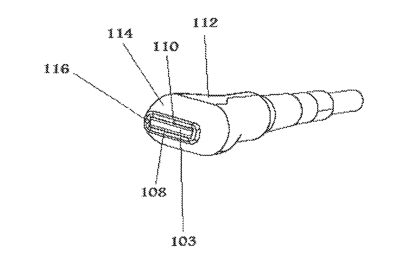
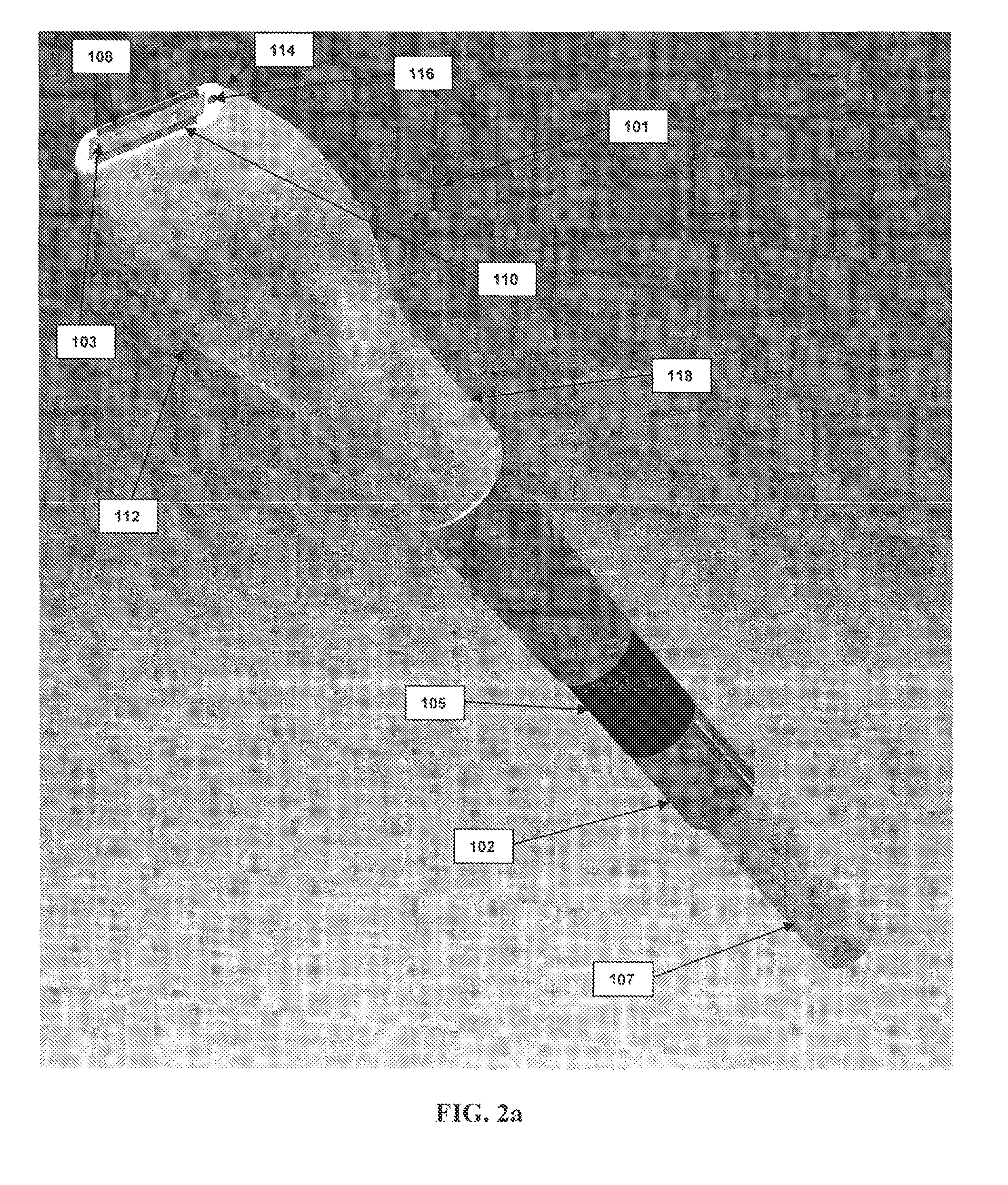
[0031]The present invention provides a photoacoustic scan head that includes laser fibers integrated into the housing of an arrayed ultrasonic transducer to allow for the delivery of uniform light energy to an acoustic imaging plane generated by the transducer. In particular, the laser fibers, which may be arranged, for example, in rectangular shaped bundles, are embedded into the housing of the transducer alongside the ultrasound elements. The integrated fiber bundle(s) are potted into the housing using a transparent potting epoxy or other resin selected to provide sufficient refraction for lens effects to be used to allow precise illumination uniformly along the acoustic imaging plane. In addition, multiple angles of illumination can be incorporated by shaping the face of the epoxy or other resin material used to pot the bundled fibers in the transducer housing. This allows the light to be delivered at a specific angle relative to the face of the transducer.

[0032]An example of a l...


PUM


Abstract

The invention disclosed herein features a photoacoustic scan head that includes laser fibers integrated into the housing of an arrayed ultrasound transducer using an optically transparent epoxy or other resin. The light-emitting ends of the fibers are positioned adjacent to the front surface of the transducer and direct laser light onto a subject being scanned by the transducer. The light beams generated by the fibers may be angled to intersect the acoustic field generated by the transducer so as to generate a photoacoustic effect in the region scanned by the transducer.

Description

FIELD OF THE INVENTION[0001]The present invention generally relates to the fields of photoacoustic imaging and medical diagnostics. More specifically, the present invention relates to a photoacoustic imaging system that includes an ultrasound transducer with integrated optical fibers that can be used to obtain photoacoustic images of a subject, such as a human or small laboratory animal, for diagnostic and other medical or research purposes.BACKGROUND[0002]Ultrasound-based imaging is a common diagnostic tool used by medical professionals in various clinical settings to visualize a patient's muscles, tendons and internal organs, as well as any pathological lesions that may be present, with real time tomographic images. Ultrasonic imaging is also used by scientists and medical researchers conducting in vivo studies to assess disease progression and regression in test subjects.[0003]Ultrasound imaging systems typically have a transducer that sends and receives high frequency sound wave...

Claims


Application Information

Patent Timeline
IPC IPC(8): A61B5/00
CPCA61B5/0095A61B8/4416A61B8/4444A61B8/483A61B5/742A61B2562/0233A61B8/4488
Inventor HIRSON, DESMONDNEEDLES, ANDREWEPHRAT, PINHASCHAGGARES, NICHOLAS CHRISTOPHER
Owner FUJIFILM SONOSITE
Why Eureka
Try Eureka