Thermal displacement compensating device for machine tool

a compensating device and machine tool technology, applied in adaptive control, program control, instruments, etc., can solve the problems of inability to satisfactorily improve the accuracy of correction, the shaft contracting, and the high-precision machining, so as to achieve the effect of improving the accuracy of thermal displacement compensation, reducing the cost, and increasing the cos

Active Publication Date: 2013-07-25
FANUC LTD
View PDF11 Cites 41 Cited by
  • Summary
  • Abstract
  • Description
  • Claims
  • Application Information

AI Technical Summary

Benefits of technology

[0017]According to the present invention, there may be provided a thermal displacement compensating device for a machine tool, capable of properly adjusting a thermal displacement compensation amount in any of states including a heat generating state, steady state, and heat dissipating state, thereby precisely compensating thermal displacement. In the thermal displacement compensating device of the invention, the thermal displacement state identification unit can identify the thermal displacement amount change state, and the coefficient calculation unit and the thermal displacement amount calculation unit can adjust the thermal displacement compensation amount based on the identified state. Thus, proper compen

Problems solved by technology

The displacement of the machine position due to the heat causes a problem in performing high-precision machining.
If the drive is stopped or slowed down, in contrast, the shafts contract due to heat dissipation.
Since the calculation formula includes additional coefficients (a heat-dissipation coefficient and a heat conduction coefficient for calculating heat conduction from adjacent sections), the precision of the correction may not be able to be satisfactorily improved by only modifying the heat-generation coefficient, in some cases.
While the coefficient is modified without regard to the state (heat generating state, steady state, or heat dissipating stat

Method used


Image

  • Thermal displacement compensating device for machine tool
  • Thermal displacement compensating device for machine tool
  • Thermal displacement compensating device for machine tool

Examples


Embodiment Construction

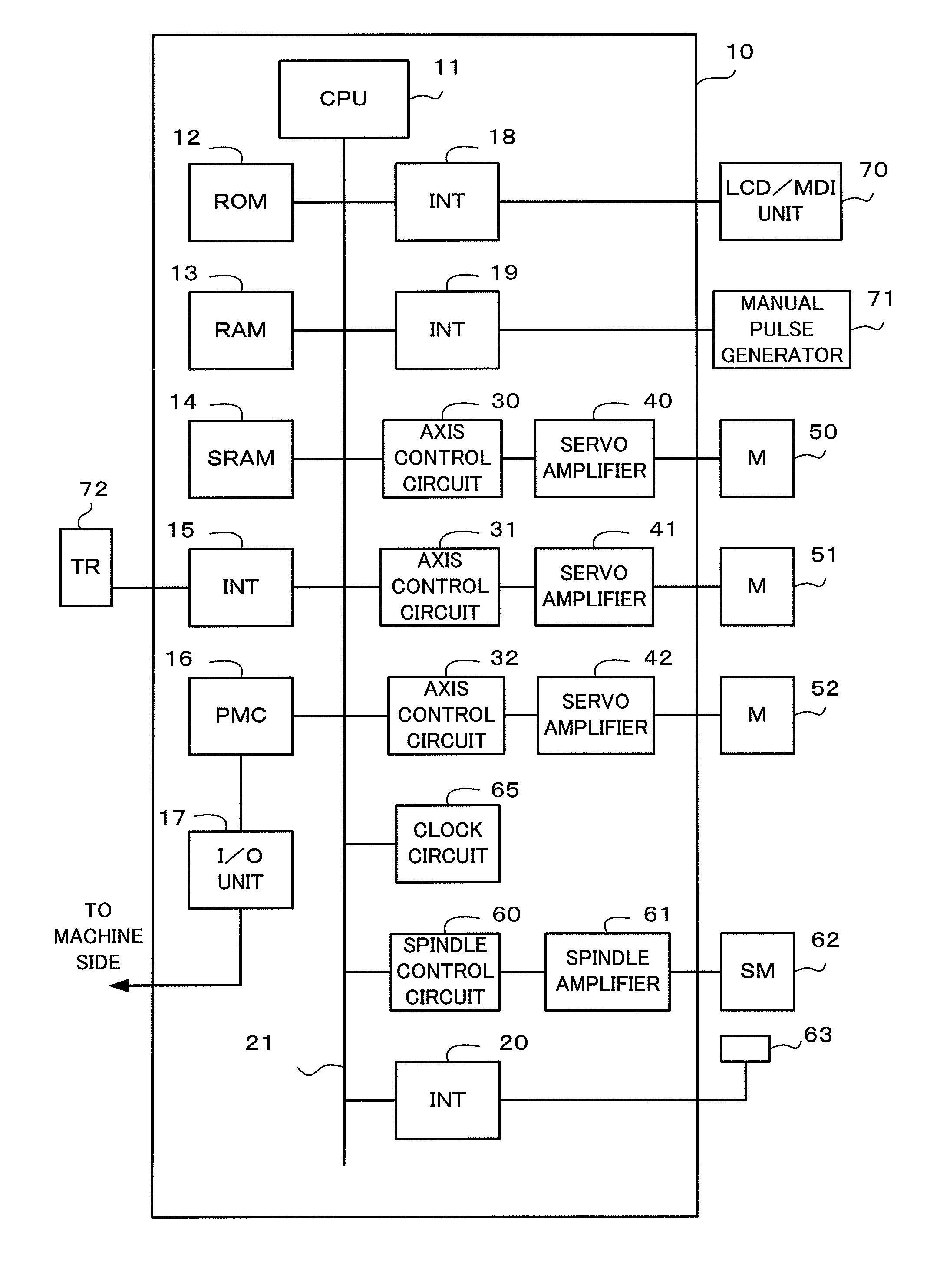
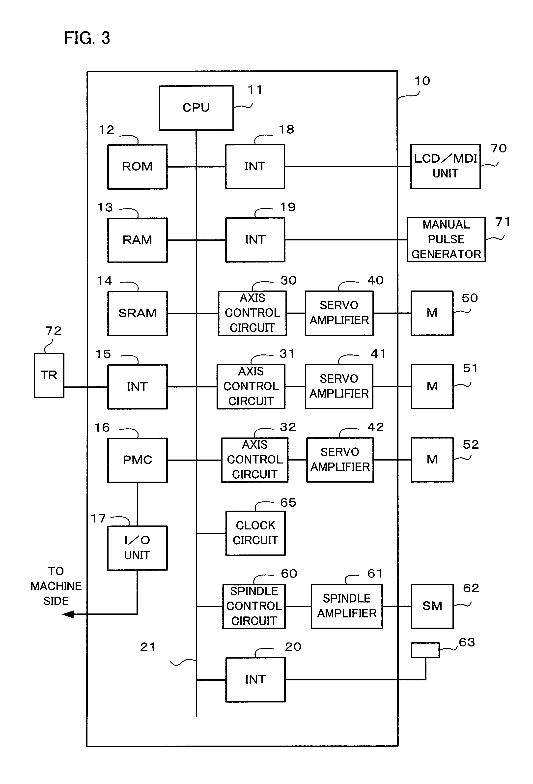
[0026]FIG. 3 is a functional block diagram showing a principal part of a numerical controller for a machine tool.

[0027]A processor (CPU) 11 of a numerical controller 10 reads a system program stored in a ROM 12 through a bus 21 and generally controls the numerical controller 10 according to the system program. A RAM 13 is loaded with temporary calculation data and display data, various data input by an operator through an LCD / MDI unit 70, etc.

[0028]An SRAM 14 is a nonvolatile memory that is backed up by a battery (not shown) such that it can maintain its memory state even when the numerical controller 10 is switched off. The SRAM 14 can be stored with a program for the measurement of an initial position, a program for thermal displacement compensation of the machine tool, a machining program (described later) read through an interface 15, a machining program input through the LCD / MDI unit 70, etc. Further, the ROM 12 is preloaded with various system programs for the execution of edi...


PUM


Abstract

A thermal displacement compensating device calculates a thermal displacement amount which is produced by heat generation or dissipation as a machine tool is actuated or stopped and changes with time. A thermal displacement compensation amount is calculated by multiplying the calculated thermal displacement amount by a coefficient. A position command is compensated by adding the thermal displacement compensation amount to the position command. On the other hand, a variation between a thermal displacement amount calculated last time and a current thermal displacement amount is determined for each predetermined time. A plurality of thermal displacement amount change states are identified based on comparison between the determined variation and a predetermined threshold. The coefficient is calculated based on the identified thermal displacement amount change state.

Description

BACKGROUND OF THE INVENTION[0001]1. Field of the Invention[0002]The present invention relates to a thermal displacement compensating device for a machine tool, and more particularly, to a device configured to adjust a thermal displacement compensation amount based on a compensation error in response to a thermal displacement change state, thereby precisely compensating thermal displacement.[0003]2. Description of the Related Art[0004]In a machine tool, a feed screw and a spindle are driven by a motor, so that they are expanded to displace the machine position by heat from the motor, frictional heat produced by the rotation of a bearing, and frictional heat from an engagement portion of the feed screw between a ball screw and a ball nut. Thus, the relative positions of a workpiece to be positioned and a tool are shifted. The displacement of the machine position due to the heat causes a problem in performing high-precision machining.[0005]The displacement of the machine position due t...

Claims


Application Information

Patent Timeline
IPC IPC(8): G05B13/00
CPCB23Q11/0007G05B19/404G05B2219/49204
Inventor MAEKAWA, SUSUMU
Owner FANUC LTD
Why Eureka
Try Eureka