Split pass economizer bank with integrated water coil air heating and feedwater biasing

a split-pass economizer and coil-type technology, which is applied in the direction of machines/engines, automatic control of ignition, lighting and heating apparatus, etc., can solve the problems of only nominal boiler efficiency improvement, wcah cannot be installed in the feedwater flow path between cold and hot banks, and cannot be installed at an intermediate location using a single traditional long flow, etc., to achieve better heat absorption, reduce space requirements, and increase thermal efficiency

Inactive Publication Date: 2013-08-01
THE BABCOCK & WILCOX CO
View PDF5 Cites 10 Cited by
  • Summary
  • Abstract
  • Description
  • Claims
  • Application Information

AI Technical Summary

Benefits of technology

[0017]The arrangement includes an intermediate WCAH 30 arranged to cool feedwater between the cold and hot economizer banks 22, 24. This parallel arrangement provides increased thermal effectiveness combined with smaller space requirements. This is an improvement over prior art economizers which could only utilize the energy efficiency advantages of a WCAH 30 if multiple economizer banks were used in series, as shown in FIG. 1, where the flue gas temperature exiting from an upstream (with respect to a direction of flue gas flow) bank is the entering flue gas temperature for a downstream (with respect to a direction of flue gas flow) bank. A preferred embodiment allows the feedwater flow to be biased between economizer banks and the WCAH 30 by using valves 44.
[0018]In the present arrangement, when the feedwater returns to the hot bank from the WCAH it can better absorb heat from the flue gas because the feedwater temperature has been lowered. The use of a WCAH between economizer passes improves boiler efficiency significantly more than arrangements that use an economizer without a WCAH, or where water only flows through a WCAH only before or after all of the economizer passes. The improved arrangement of economizer banks in parallel allows for the addition of a WCAH when there is insufficient space to install two long flow economizer banks in series (with respect to gas flow 4, as in FIG. 1), or to avoid the extra expense of installing two banks in series.

Problems solved by technology

A problem with the prior art design shown in FIG. 1 is that it requires two full long flow economizer banks placed in series relative to the gas flow 4.
Thus, without at least two separate long flow economizer banks, a WCAH 30 cannot be installed in the feedwater flow path between cold and hot banks.
A WCAH can theoretically be installed upstream or downstream of a single bank economizer, but will offer only nominal boiler efficiency improvement if it is not between two economizer banks in the feedwater flow path.
A WCAH cannot, however, be installed at an intermediate location using a single traditional long flow (e.g. mini-header) type economizer bank.
There is no practical location to integrate a WCAH 30 using the prior art collection headers, particularly since the WCAH 30 must be placed outside of the hot flue gas flow, typically outside the boiler wall, to function.
At the same time, it is often not practical or desirable to install two full separate economizer banks spanning the gas flow path as shown in FIG. 1.
In some cases, using two separate banks in series is impractical or requires too much space, particularly when a pre-existing space is being refitted.
Installing two separate full economizer banks can also add unwanted expense.

Method used


Image

  • Split pass economizer bank with integrated water coil air heating and feedwater biasing
  • Split pass economizer bank with integrated water coil air heating and feedwater biasing
  • Split pass economizer bank with integrated water coil air heating and feedwater biasing

Examples


Embodiment Construction

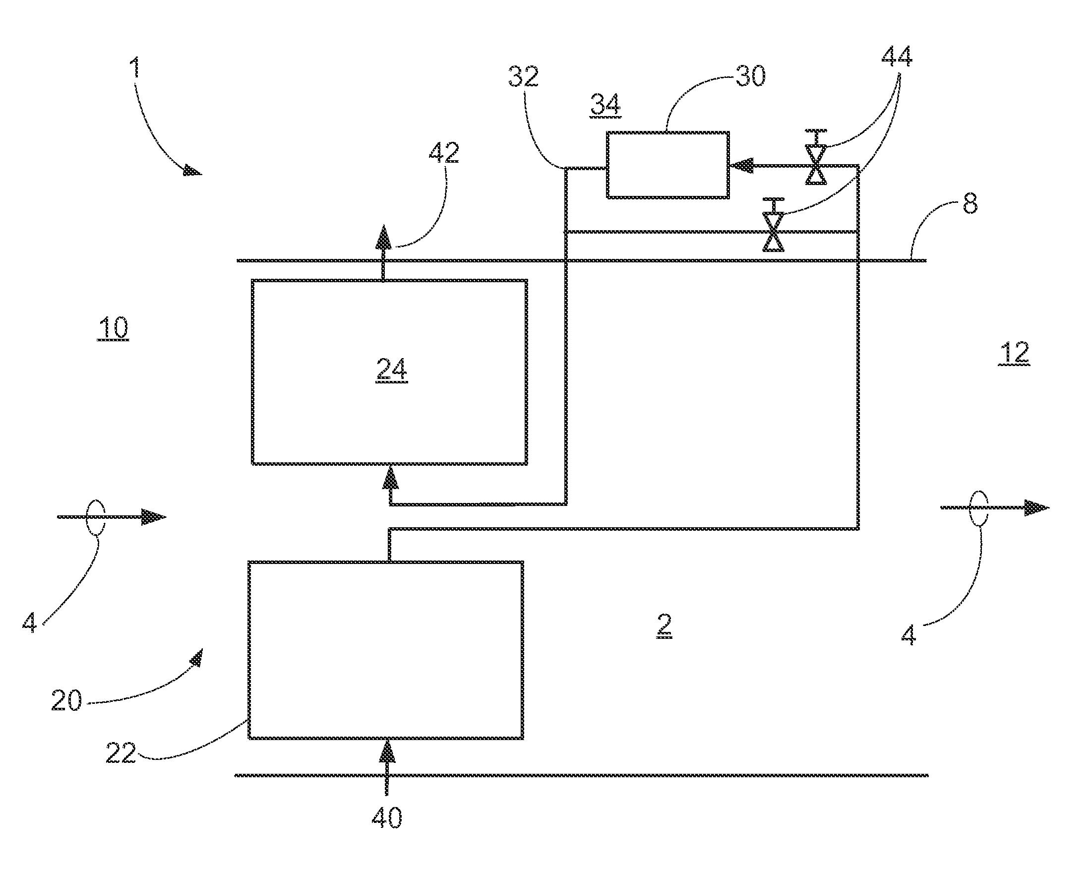
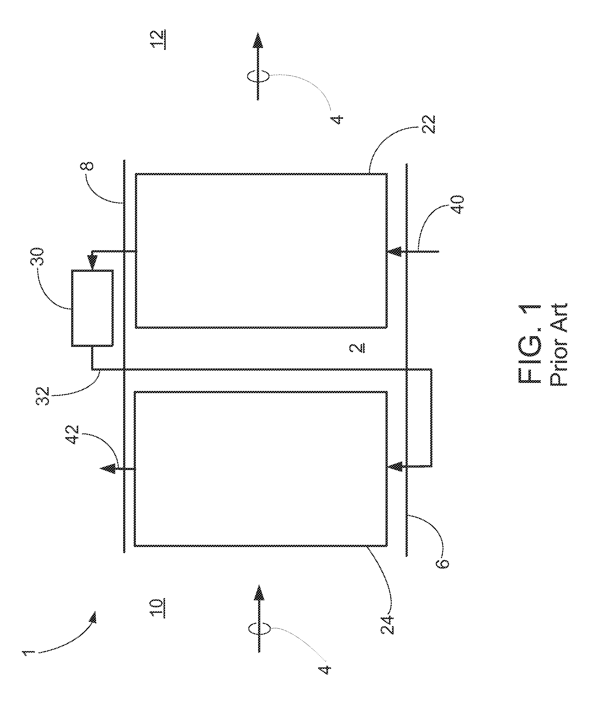
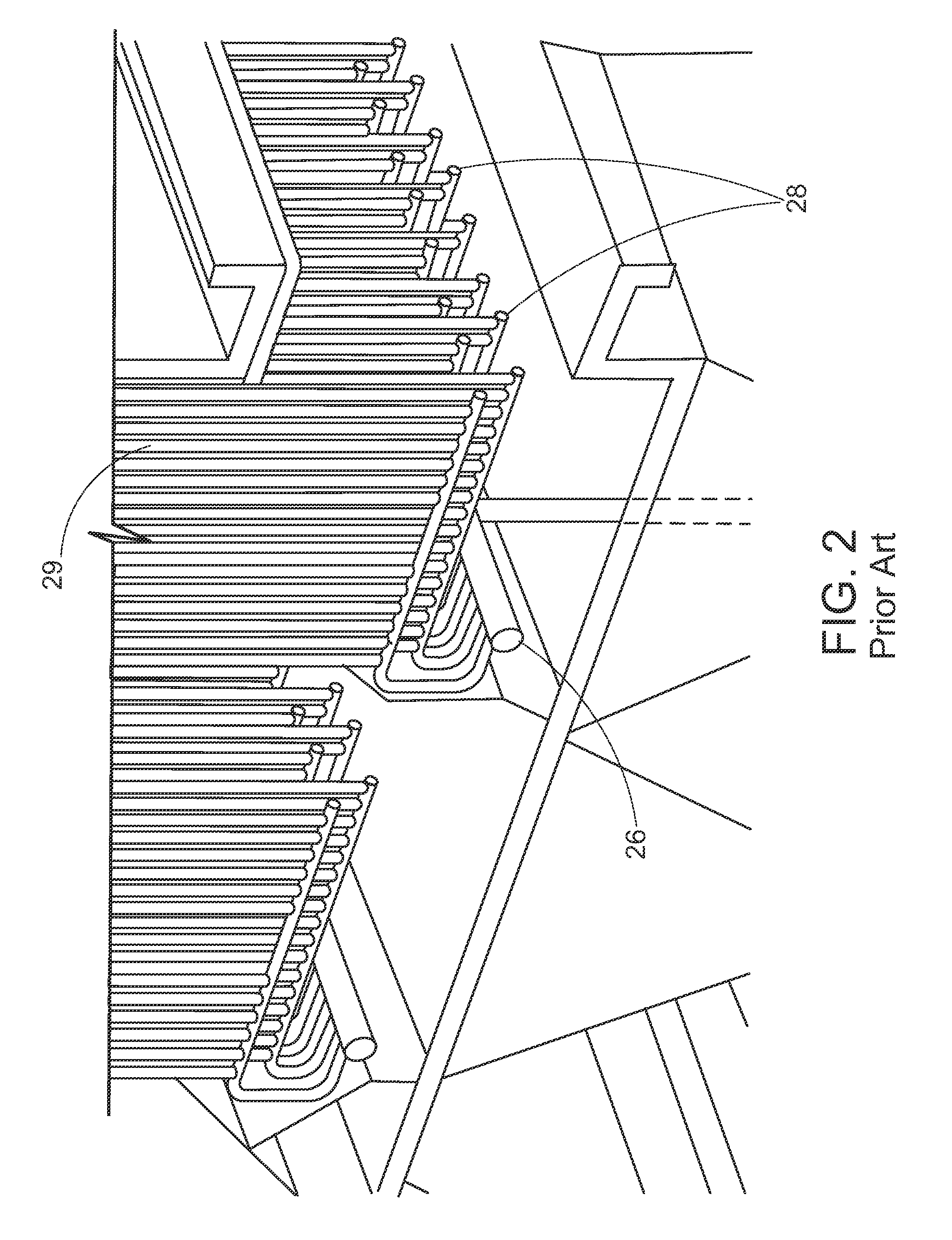
[0037]A more complete understanding of the processes and apparatuses disclosed herein can be obtained by reference to the accompanying drawings. These figures are merely schematic representations based on convenience and the ease of demonstrating the existing art and / or the present development, and are, therefore, not intended to indicate relative size and dimensions of the assemblies or components thereof.

[0038]Although specific terms are used in the following description for the sake of clarity, these terms are intended to refer only to the particular structure of the embodiments selected for illustration in the drawings, and are not intended to define or limit the scope of the disclosure. In the drawings and the following description below, it is to be understood that like numeric designations refer to components of like function.

[0039]It should be noted that many of the terms used herein are relative terms. For example, the terms “inlet” and “outlet” are relative to a direction ...


PUM


Abstract

An apparatus for using a water coil air heater with a single bank economizer. A boiler economizer arrangement includes an economizer bank which has separate hot pass bank and cold pass bank economizer portions in a parallel arrangement, each facing the same flow of hot flue gas. Feedwater enters the cold pass bank economizer where it is heated by the hot flue gas, and then flows to a water coil air heater away from the hot flue gas. The feedwater dissipates heat energy in the water coil air heater which may be used to heat air bound for combustion. The feedwater continues into the hot pass bank economizer portion of the economizer arrangement where it absorbs additional heat from the flue gas. The heated feedwater flows out of the economizer arrangement and may be subject to additional heating by a boiler or other heat exchanger.

Description

CROSS-REFERENCE TO PRIORITY APPLICATION[0001]This application claims the benefit of U.S. provisional Application No. 61 / 593,556 filed Feb. 1, 2012. U.S. Provisional Patent Application No. 61 / 593,556 filed Feb. 1, 2012 is hereby incorporated by reference in its entirety.FIELD AND BACKGROUND OF THE INVENTION[0002]The present invention relates generally to boiler economizers for maximizing heat transfer from hot products of combustion to water, and in particular to economizer bank arrangements where hot banks and cold banks are arranged next to each other so that a water coil air heater (WCAH) can be used without requiring multiple banks in series relative to the gas flow.[0003]Economizers and air heaters perform key functions in energy generation by increasing overall boiler thermal efficiency by recovering energy from flue gas before it is exhausted to the atmosphere. Typically for each 40 F (22 C) that the flue gas is cooled by an economizer—sometimes in conjunction with an air heat...

Claims


Application Information

Patent Timeline
Patent Type & Authority Applications(United States)
IPC IPC(8): F22D1/38F22D1/02
CPCF22D1/02F22D1/38F22D1/36
Inventor GRIES, JEFFREY J.HINER, LARRY A.STRIRGWOLT, WILLIAM R.
Owner THE BABCOCK & WILCOX CO
Why Eureka
Try Eureka