Double drive shaft motor of magnetic flux modulation type

a technology of magnetic flux and motor, which is applied in the direction of dynamo-electric gears, magnetic circuit shapes/forms/construction, dynamo-electric machines, etc., can solve the problems of reducing the overall amount of stator winding wounds in stators, limiting the size of field rotors, and difficult to produce strong field magnetic forces. , to achieve the effect of enhancing the entire performance of the double drive shaft motor, preventing the size of the magneti

Inactive Publication Date: 2013-08-01
DENSO CORP
View PDF8 Cites 8 Cited by
  • Summary
  • Abstract
  • Description
  • Claims
  • Application Information

AI Technical Summary

Benefits of technology

[0015]This structure prevents the size of the magnetic modulation rotor in the double drive shaft motor from being decreased. This structure allows the double drive shaft motor to have an increased amount of the stator winding in the stator and a large number of magnets in the field rotor. As a result, this makes it possible to output a large output torque and power.
[0016]Still further, because the structure previously described makes it possible to form a space at a radially inner side or a radially outer side of the magnetic modulation rotor where the stator and the field rotor are not arranged, it is possible to arrange a bearing, a transmission device and etc., in this space or to use this space as air flow passage through which cooling air passes. This structure makes it possible to enhance the entire performance of the double drive shaft motor.

Problems solved by technology

This structure limits the size of the field rotor in the conventional power machine, and it becomes difficult to produce a strong field magnetic force.
In addition, when the size of the stator is decreased in order to increase the field magnetic force of the field rotor, this decreases the overall amount of the stator winding wound in the stator, and as a result, decreases the magnitude of generated torque.
Still further, it is difficult to adequately fix the soft magnetic material of the magnetic modulation rotor because a magnetic flux penetrates through the soft magnetic material.
However, the conventional structure using such an insulation member is relatively weakly attached to the magnetic modulation rotor made of the soft magnetic material.
Accordingly, it is difficult to arrange additional members such as bearings and rotation position detection sensors, and further difficult to form any additional space through which cooling air flows in addition to the rotating shaft in the inside of the field rotor in the conventional power machine previously described.

Method used


Image

  • Double drive shaft motor of magnetic flux modulation type
  • Double drive shaft motor of magnetic flux modulation type
  • Double drive shaft motor of magnetic flux modulation type

Examples


first exemplary embodiment

[0031

[0032]A description will be given of a double drive shaft motor of a magnetic flux modulation type according to the first exemplary embodiment of the present invention with reference to FIG. 1 to FIG. 7.

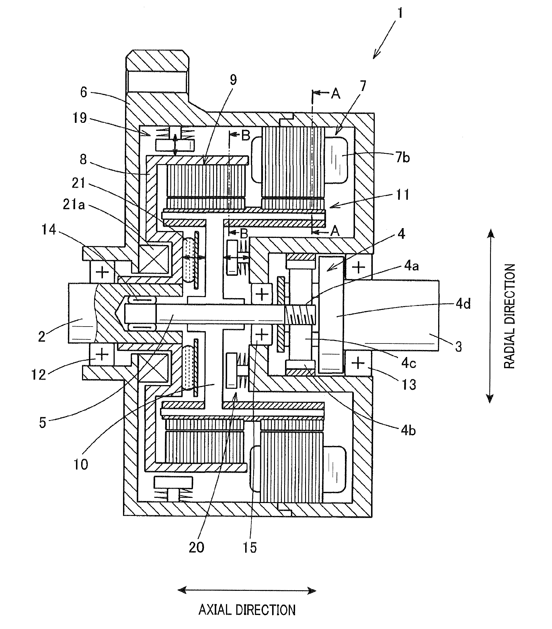
[0033]FIG. 1 is a view showing a vertical cross section of the double drive shaft motor according to the first exemplary embodiment of the present invention.

[0034]As shown in FIG. 1, the double drive shaft motor 1 according to the first exemplary embodiment has a first rotating shaft 2, a second rotating shaft 3, a third rotating shaft 5, a stator 7, a field rotor 9, a magnetic modulation rotor 11, etc.

[0035]The first rotating shaft 2 receives a rotational power transmitted from an internal combustion engine of a hybrid vehicle (not shown). When receiving the rotational power, the first rotating shaft 2 rotates. The second rotating shaft 3 is engaged with a wheel drive system. The third rotating shaft is engaged with the second rotating shaft 3 through a reduction gear device 4....

second exemplary embodiment

[0091

[0092]A description will be given of a double drive shaft motor 1A according to a second exemplary embodiment of the present invention with reference to FIG. 8.

[0093]FIG. 8 is a view showing a basic structure of the double drive shaft motor 1A according to the second exemplary embodiment of the present invention. The same components between the double drive shaft motor 1A according to the second exemplary embodiment and the double drive shaft motor 1 according to the first exemplary embodiment will be designated with the same reference characters and numbers. The explanation of the same components is omitted here for brevity.

[0094]As shown in FIG. 8, the field rotor 9A is shifted in a radial direction viewed from the coil end of the stator 7. That is, as shown in FIG. 8, the field rotor 9A is arranged at a radially inside viewed from the coil end of the stator 7. This structure of the double drive shaft motor 1A makes it possible to have the same effects of the double drive sha...

third exemplary embodiment

[0097

[0098]A description will be given of a double drive shaft motor 1B according to a third exemplary embodiment of the present invention with reference to FIG. 9.

[0099]FIG. 9 is a view showing a basic structure of the double drive shaft motor 1B according to the third exemplary embodiment of the present invention.

[0100]The same components between the double drive shaft motor 1B according to the third exemplary embodiment and the double drive shaft motor 1 according to the first exemplary embodiment will be designated with the same reference characters and numbers. The explanation of the same components is omitted here for brevity.

[0101]As shown in FIG. 9, the double drive shaft motor 1B according to the third exemplary embodiment has the structure in which the field rotor 9B faces one end surface of the magnetic modulation rotor 11B in an axial direction of the double drive shaft motor 1B. The magnetic modulation rotor 11B has the soft magnetic material members 17B which form the ...


PUM


Abstract

In a double drive shaft motor, a stator and a field rotor are arranged at a radially outer side of a magnetic modulation rotor. The stator and the field rotor are arranged in series in an axial direction of the motor. This structure increases an amount of a winding coil of the stator and magnets in the field rotor, and an output torque of the motor. When a field magnetic flux passes through soft magnetic material members in the magnetic modulation rotor, because the generation and the reception of the magnetic flux can occur at a radially same side of the magnetic modulation rotor, this structure cancels an eddy current generated in the soft magnetic members and supporting members made of non-magnetic metal which tightly support the soft magnetic member. This structure provides a reduced axial size of the motor with high performance.

Description

CROSS-REFERENCE TO RELATED APPLICATION[0001]This application is related to and claims priority from Japanese Patent Application No. 2012-16049 filed on Jan. 30, 2012, the contents of which are hereby incorporated by reference.BACKGROUND OF THE INVENTION[0002]1. Field of the invention[0003]The present invention relates to double drive shaft motors of a magnetic flux modulation type, to be mounted on hybrid vehicles such as hybrid electric vehicles and used as a drive motor therefor, having an improved structure capable of converting rotation speed and torque of power between two power machines, and for executing an electric power division control such as addition and subtraction of the power.[0004]2. Description of the Related Art[0005]There have been proposed various types of rotary machines capable of converting a high-speed rotation power generated by an internal combustion engine to a low-speed rotation power by gradually changing a transmission gear ratio in a transmission devic...

Claims


Application Information

Patent Timeline
Patent Type & Authority Applications(United States)
IPC IPC(8): H02K1/06
CPCH02K51/00H02K7/11H02K16/02H02K1/06H02K16/00H02K7/112
Inventor KUSASE, SHINFUKUSHIMA, AKIRA
Owner DENSO CORP
Why Eureka
Try Eureka