Enhanced target detection using dispersive vs non-dispersive scatterer signal processing

a scatterer signal and target detection technology, applied in the direction of reradiation, measurement devices, instruments, etc., can solve the problems of slow-moving or stationary radar platforms limited by radar dwell duration, difficult to separate targets from clutter, etc., to improve doppler resolution, improve target detection efficiency, and improve the effect of target detection

Active Publication Date: 2013-08-01
RAYTHEON CO
View PDF10 Cites 19 Cited by
  • Summary
  • Abstract
  • Description
  • Claims
  • Application Information

AI Technical Summary

Benefits of technology

[0007]Further aspects of embodiments of the present invention are directed toward discriminating between dispersive clutter-like returns versus non-dispersive target-like returns using the location of the roots of the linear prediction coefficient polynomial. In addition, aspects of embodiments of the present invention are directed toward fast implementations of this discrimination algorithm. Still further aspects of embodiments of the present invention enhance target detection by using short dwells to achieve required radar capacity. In addition, aspects of embodiments of the present invention are directed to providing dismount detection at low mean Doppler velocity (MDV). Further aspects of embodiments of the present invention are directed toward applying the Burg extrapolation algorithm to improve Doppler resolution by a factor of 3.
[0008]In an exemplary embodim

Problems solved by technology

While trying to detect dismounts and other slow-moving targets, a slow-moving or stationary radar platform is limited by the radar dwell duration (radar capacity requirements) and Doppler extent of the clutter.
The problem is exacerbated by factors such as short duration dwells, wind-blown ground

Method used


Image

  • Enhanced target detection using dispersive vs non-dispersive scatterer signal processing
  • Enhanced target detection using dispersive vs non-dispersive scatterer signal processing
  • Enhanced target detection using dispersive vs non-dispersive scatterer signal processing

Examples


Embodiment Construction

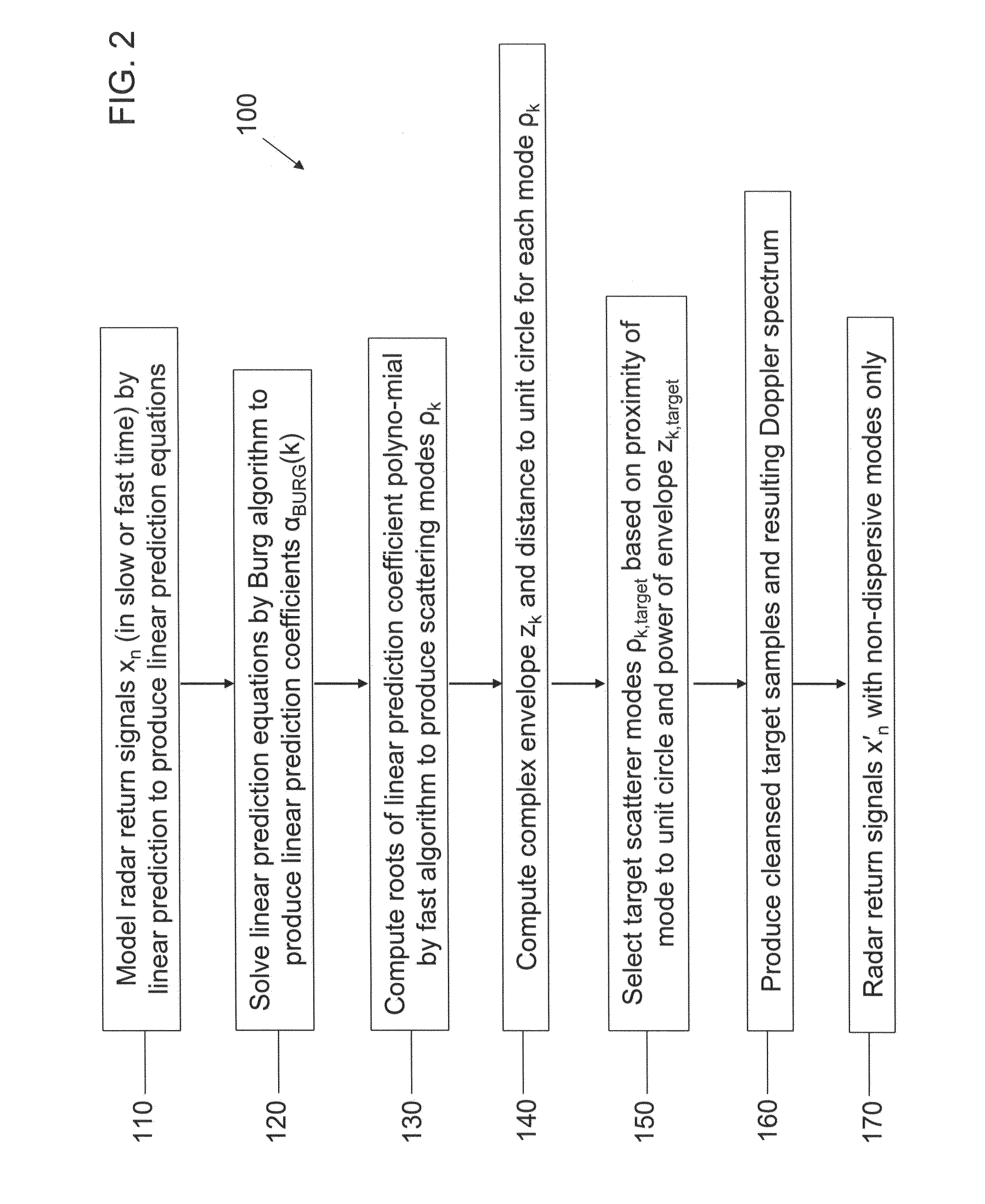
[0045]Hereinafter, exemplary embodiments of the invention will be described in more detail with reference to the accompanying drawings. In the drawings, like reference numerals refer to like elements throughout. While the exemplary embodiments are described in terms of signals in the slow time domain (that is, pulse-to-pulse time samples), the techniques are equally valid in the fast frequency domain (that is, the Fourier transform of the fast time domain, e.g., samples within a radar pulse) to one of ordinary skill in the art.

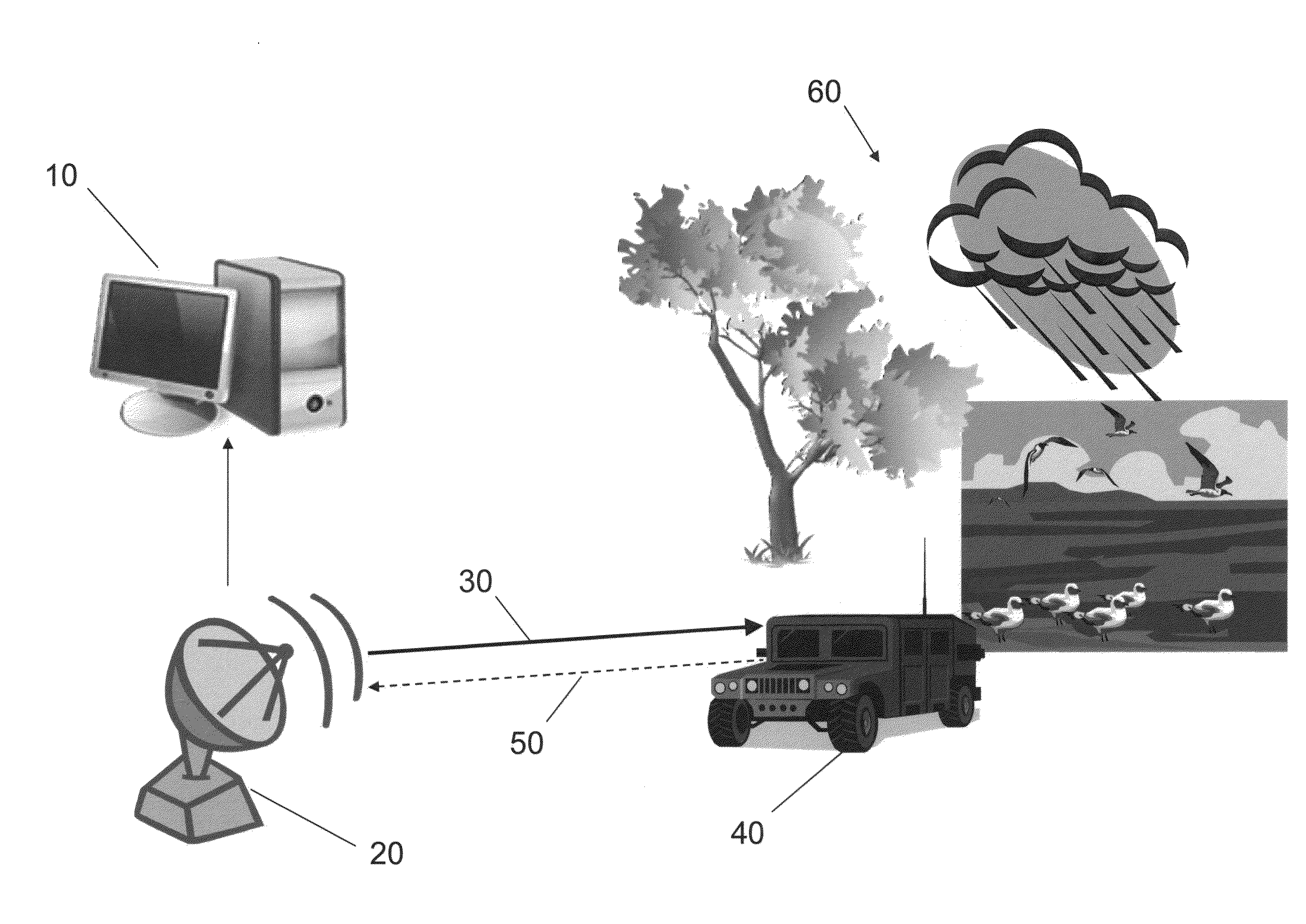
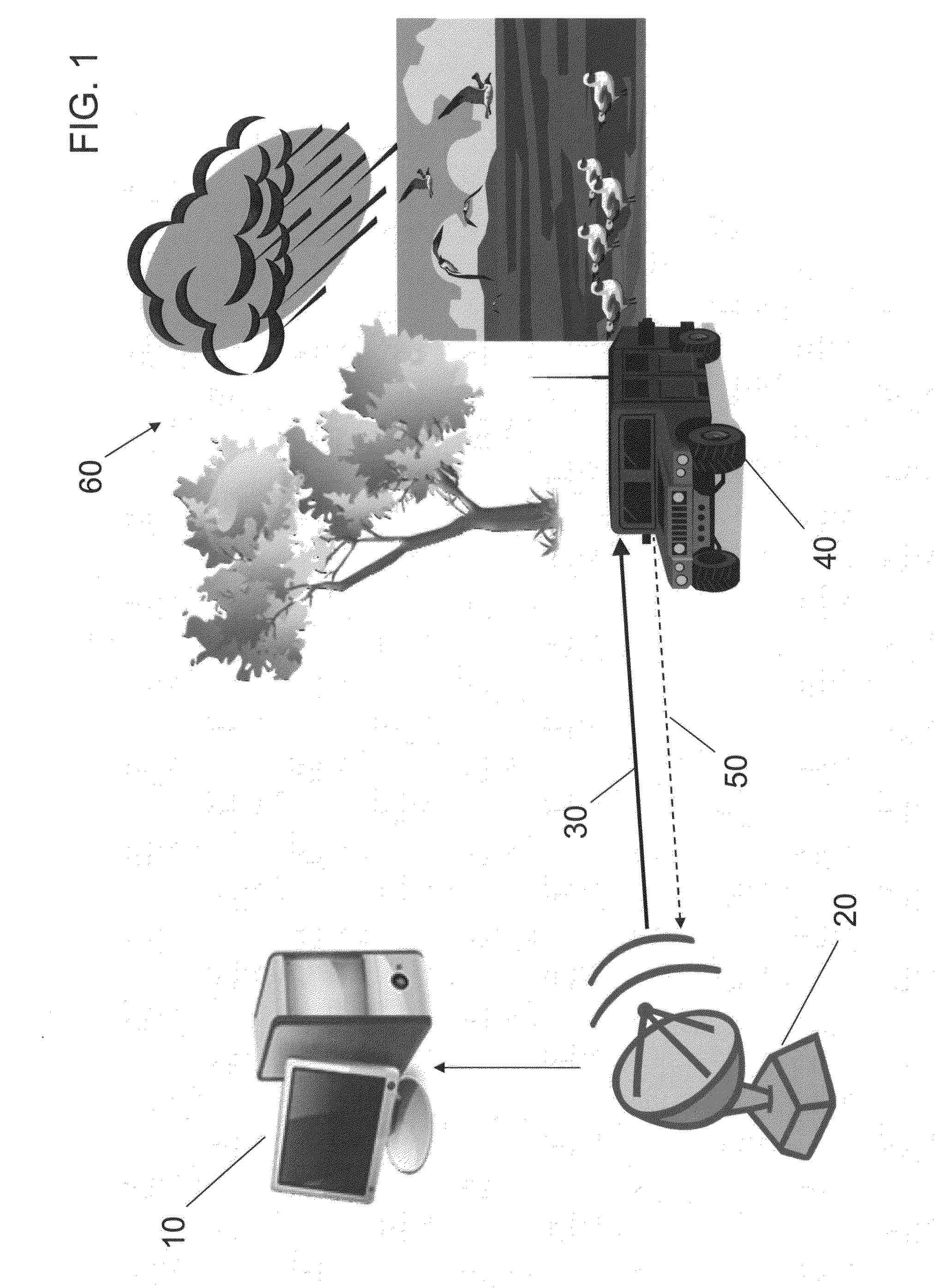
[0046]In general, the principle of discriminating between dispersive and non-dispersive signals applies to a wide variety of transmitted radar waveforms, dwell durations, waveform bandwidths, etc. As a non-limiting example, certain monitoring and tracking applications require the detection of dismounts and other slow-moving targets in the presence of various types of clutter while using short dwell durations. Short dwell durations, which can be 25-30 milliseco...


PUM


Abstract

A method of target discrimination and identification, on a computer including a processing unit and a non-volatile storage device, from a radar signal having a plurality of radar return signals, is presented. The method includes: modeling, on the computer, the radar return signals by linear prediction to produce linear prediction equations; solving, on the computer, the linear prediction equations by the Burg algorithm to produce linear prediction coefficients for a linear prediction coefficient polynomial; computing, on the computer, roots of the linear prediction coefficient polynomial to produce scattering modes; computing, on the computer, a distance of each of the scattering modes to a unit circle; computing, on the computer, a complex envelope for each mode of the scattering modes; and selecting, on the computer, target scattering modes from among the scattering modes based on the distance of the mode to the unit circle and the complex envelope of the mode.

Description

STATEMENT REGARDING FEDERALLY SPONSORED RESEARCH OR DEVELOPMENT[0001]This invention disclosure is related to Government contract number HR0011-09-C-0036, entitled “ISIS Phase 3 Demonstrator System Contract.” The U.S. Government has certain rights in this invention.BACKGROUND[0002]1. Field[0003]Aspects of embodiments of the present invention are directed toward enhanced target detection using dispersive versus non-dispersive scatterer signal processing.[0004]2. Description of Related Art[0005]While trying to detect dismounts and other slow-moving targets, a slow-moving or stationary radar platform is limited by the radar dwell duration (radar capacity requirements) and Doppler extent of the clutter. The problem is exacerbated by factors such as short duration dwells, wind-blown ground clutter, rain clutter, and bird-flock clutter. It can be difficult to separate target from clutter returns when the clutter is spread in Doppler (both may be identified as targets). The clutter (and oth...

Claims


Application Information

Patent Timeline
IPC IPC(8): G01S13/04
CPCG01S13/5244G01S7/415
Inventor ABATZOGLOU, THEAGENIS J.HO, KENNETHHUI, LEO H.
Owner RAYTHEON CO
Why Eureka
Try Eureka