System and method for automated optical inspection of industrial gas turbines and other power generation machinery with articulated multi-axis inspection scope

an industrial gas turbine and optical inspection technology, applied in the direction of television systems, machines/engines, instruments, etc., can solve the problems of time-consuming, repetitive, and difficult positioning of inspection apparatuses, and achieve the effect of reducing the total time needed and resuming power generation more quickly

Active Publication Date: 2013-08-01
SIEMENS ENERGY INC
View PDF12 Cites 46 Cited by
  • Summary
  • Abstract
  • Description
  • Claims
  • Application Information

AI Technical Summary

Benefits of technology

[0012]Accordingly, potential objects of the present invention, jointly or severally among others, are to create optical camera inspection systems and methods for power generation machinery, (including by way of non-limiting example steam or gas turbines and generators) that compared to known inspection apparatus and methods: reduce total scheduled maintenance period time and individual inspection cycle time; position inspection apparatus consistently and repetitively within an individual machine's inspection cycle or within inspection cycles of multiple different machines, with minimized risk of damage to machine internal components and high image quality; and that help to equalize inspection skill level and productivity among different inspection teams.

Problems solved by technology

Inspection apparatus positioning is challenging due to the complex manipulation paths between components in a gas turbine.
Improper positioning of inspection apparatus within a turbine potentially can damage turbine internal components.
In summary, known manual camera inspection procedures and inspection system manipulation are time consuming, repetitive in nature, and often require assistance of an inspection team of multiple personnel.
The “human factor” required for known manual camera inspection procedures and inspection system manipulation introduces undesirable inspection process variances based on human skill level differences.

Method used


Image

  • System and method for automated optical inspection of industrial gas turbines and other power generation machinery with articulated multi-axis inspection scope
  • System and method for automated optical inspection of industrial gas turbines and other power generation machinery with articulated multi-axis inspection scope
  • System and method for automated optical inspection of industrial gas turbines and other power generation machinery with articulated multi-axis inspection scope

Examples


embodiment 60

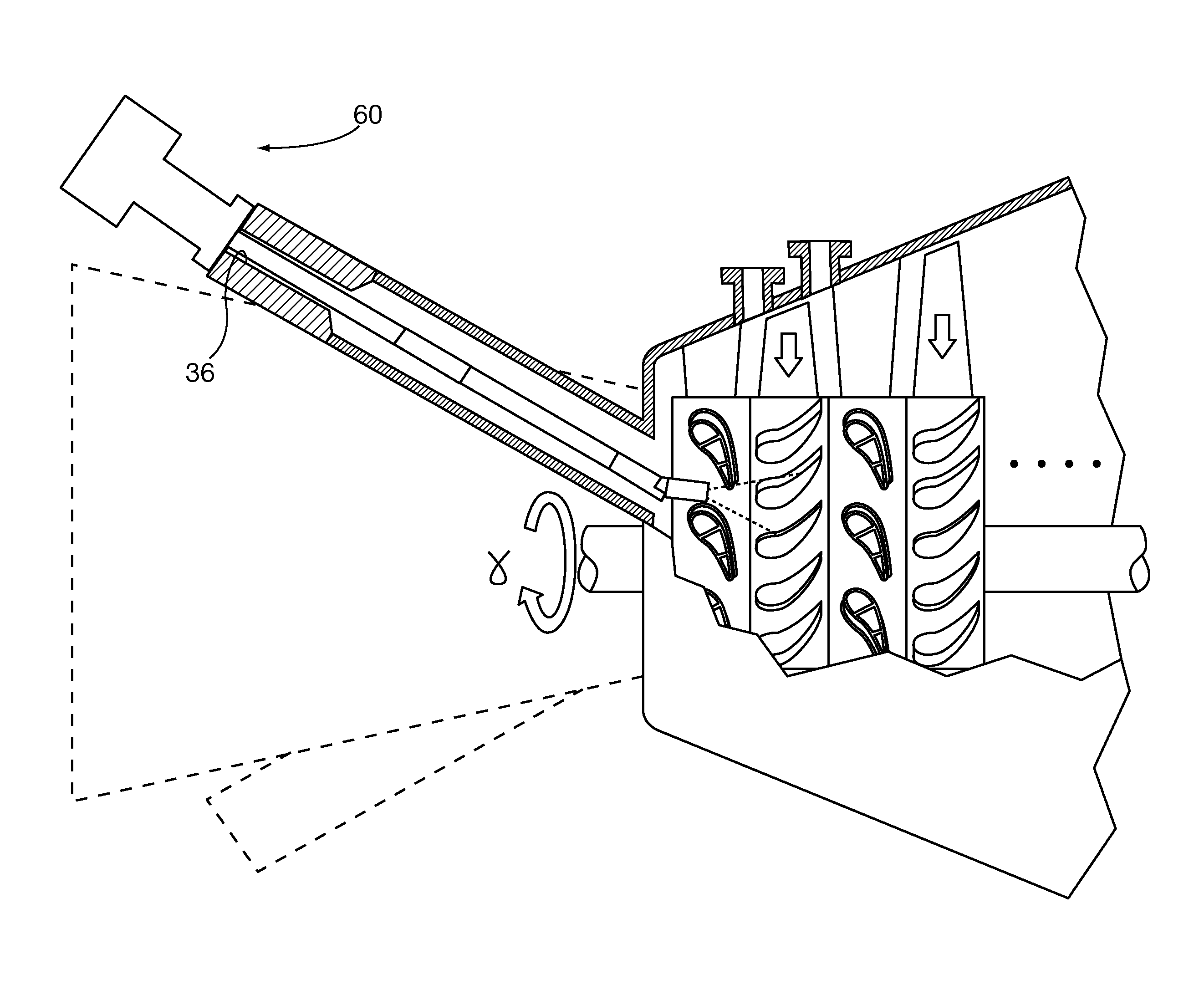
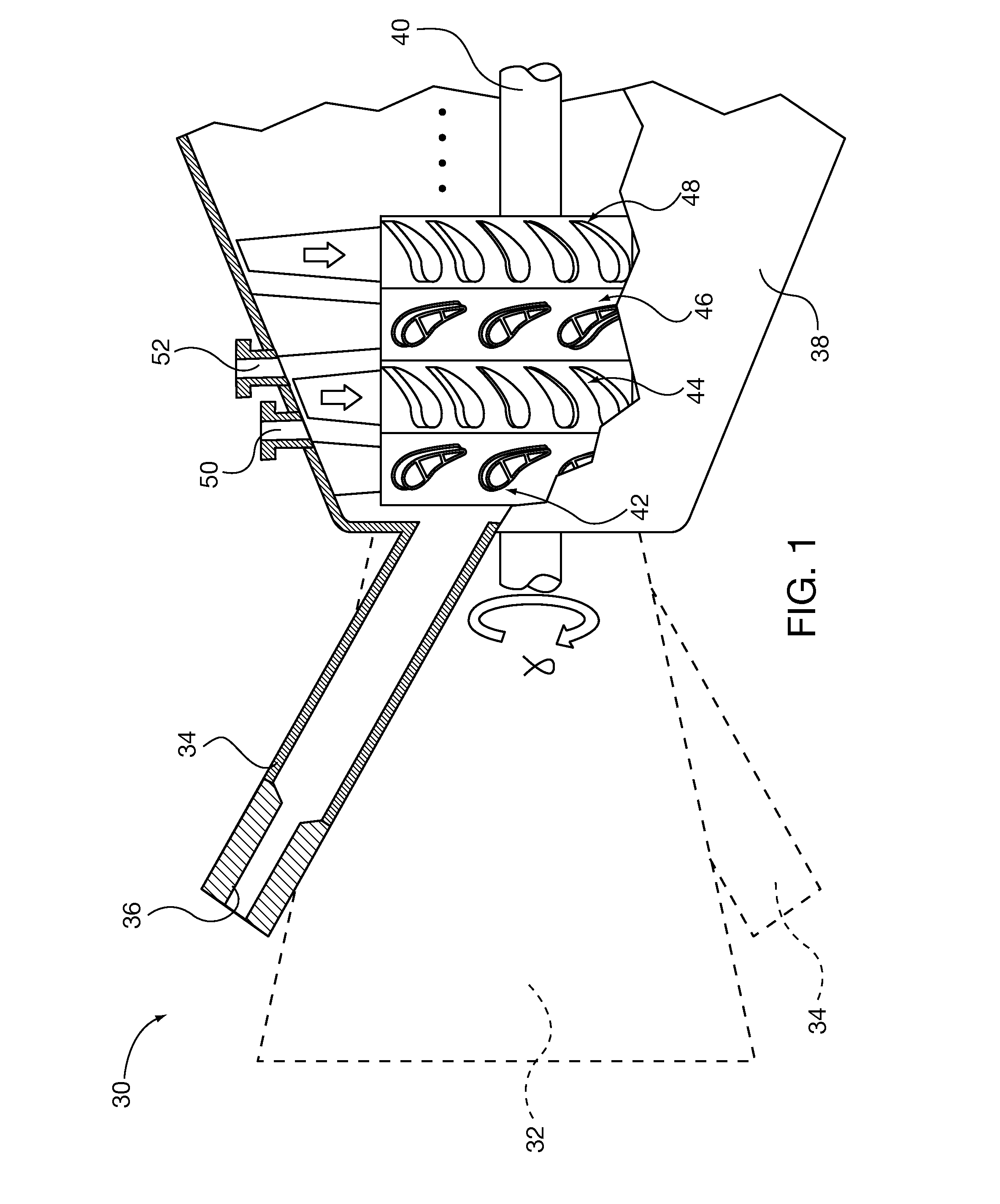
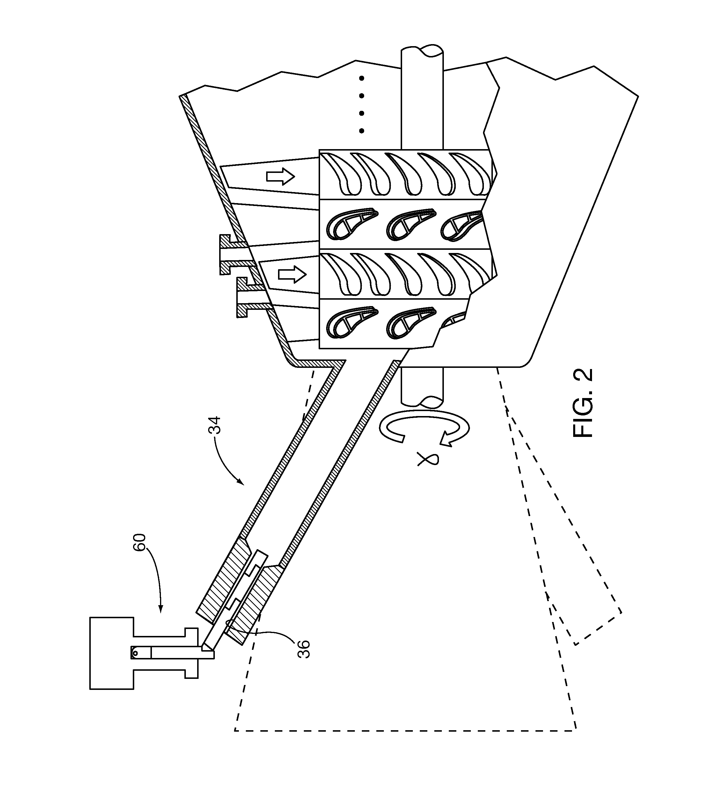
[0045]FIGS. 2-4 show inspection of a gas turbine by insertion (FIG. 2) of an articulated inspection scope embodiment 60 into a combustor 34 inspection port 36. For maneuvering clearance of the scope 60 about the confines of a gas turbine installation, inspection scope 60 has a folding knuckle, so that the scope can be folded into a generally L-shape profile about half as long as an elongated scope. Once the 60 is positioned within the inspection port 36, the knuckle is straightened, as shown in FIG. 3. After the inspection scope 60 is affixed to the inspection port 36 it may be utilized to inspect to combustor internal components by rotating and extending its camera head. In FIG. 4, as the scope 60 is further extended and its camera head articulated images of the Row 1 vanes and leading edge of Row 1 blades may be acquired. If the turbine rotor is in turning mode, images of all Row 1 blades may be captured as they rotate past the camera head field of view.

[0046]Referring to FIG. 5, ...

embodiment 50

[0067]As shown in FIGS. 19 and 20 the inspection scope 220 embodiment is mounted to a gas turbine inspection port (here a Row 1 inspection port 50) by mounting flange 222. Linear drive 224 with an associated servo motor and encoder translates the inspection scope in the telescoping extension position motion degree T. Rotational drive 226 with an associated servo motor and encoder rotates the inspection scope in the camera rotate / pan motion degree θ. Bore scope 228 is mechanically coupled to the linear drive 224 and rotational drive 226, and has a camera head 230 that captures within its field of view (FOV). The camera head 230 includes a pivoting prism 232 whose motion in the articulation Φ motion degree is imparted by an associated servo motor and encoder. The bore scope 228 is of known construction and includes fiber optic lenses 234 and auxiliary external lighting (not shown) that illuminate and transmit images within the camera head field of view to camera 336. The camera 236 ma...


PUM


Abstract

Internal components of power generation machinery, such as gas and steam turbines are inspected with an optical camera inspection system that is capable of automatically positioning the camera field of view (FOV) to an area of interest within the machinery along a pre-designated navigation path and capturing images without human intervention. Automatic camera positioning and image capture can be initiated automatically or after receipt of operator permission. The pre-designated navigation path can be defined by operator manual positioning of an inspection scope within the power machine or a similar one of the same type and recording of positioning steps for future replication. The navigation path can also be defined by virtual simulation. The inspection system includes an articulated multi-axis inspection scope.

Description

REFERENCE TO CO-PENDING APPLICATIONS[0001]This application claims the benefit of co-pending United States utility patent application entitled “System And Method For Automated Optical Inspection Of Industrial Gas Turbines And Other Power Generation Machinery”, filed concurrently herewith and assigned serial number (unknown), Attorney Docket No. 2011P28983US, and co-pending United States utility patent application entitled “System And Method For Automated Optical Inspection Of Industrial Gas Turbines And Other Power Generation Machinery With Multi-Axis Inspection Scope”, filed concurrently herewith and assigned serial number (unknown), Attorney Docket No. 2011P22742US, all of which are incorporated by reference herein.BACKGROUND OF THE DISCLOSURE[0002]1. Field of the Invention[0003]The invention relates to optical camera systems for nondestructive internal inspection of industrial gas turbines and other power generation machinery, including by way of non-limiting example steam turbine...

Claims


Application Information

Patent Timeline
Patent Type & Authority Applications(United States)
IPC IPC(8): H04N7/18
CPCF01D21/003G02B23/2476G01N21/954G01M15/14
Inventor HATCHER, CLIFFORDRUHGE, FORREST R.LEMIEUX, DENNIS H.BHATNAGAR, HIMANSHUGENC, YAKUPHATLEY, RICHARD
Owner SIEMENS ENERGY INC
Why Eureka
Try Eureka