Three-phase soft-switched pfc rectifiers

a pfc rectifier, three-phase technology, applied in the field of frontend rectifiers, can solve the problems of introducing a distortion in the average phase current, reducing the efficiency of thd,

Active Publication Date: 2013-08-01
DELTA ELECTRONICS INC
View PDF2 Cites 64 Cited by
  • Summary
  • Abstract
  • Description
  • Claims
  • Application Information

AI Technical Summary

Problems solved by technology

Generally, the major obstacle to achieving a better THD is relatively long discharging times of the boost inductors compared to their charging times. Namely, the charging currents of the inductors (during the intervals the switch is on) are proportional to their respective phase voltages and, therefore, do not contribute to current distortion.
However, the discharging current of each inductor (during the intervals the switch is off) is proportional to differences between the output voltage and all three-phase voltages, which introduces a distortion in the average phase currents.
Since the output voltage in the circuit in FIG. 1 is already high (around 750 V for 380-V three-phase line-to-line input) because the boost operation requires that the output voltage is greater than twice the peak phase voltage, improvement of THD by increasing output voltage is not practical.
Namely, an output voltage increase would require components with higher voltage ratings that are generally more expensive, as well as less efficient due to their increased conduction and switching losses.
However, the improvements obtained by the reported harmonic-injection techniques are relatively modest.
While the elimination of the rectifiers helps improve efficiency, it makes the interleaving of the circuit in FIG. 5 impossible, which may be a drawback since interleaving is often used to extend the power range of converters operating in DCM or at the CCM / DCM boundary.
One of the major issues of the two-switch three-phase rectifiers shown in FIGS. 2-5 is their EMI performance and, in particular, their common-mode noise.
Furthermore, in the implementations shown in FIGS. 4 and 5 without split capacitors, the load is also subject to these voltage changes, exacerbating the common-mode noise problem.
As a result, these circuits typically require multi-stage EMI filters, which increases their cost and size.
Another major issue with the above implementations is that they do not simultaneously provide PFC and voltage balancing of the split capacitors when load is connected across the capacitors.
To use the split capacitor approach, these circuit needs to be supplemented with a voltage balancing circuit, which further increases the cost and may also affect its size.

Method used


Image

  • Three-phase soft-switched pfc rectifiers
  • Three-phase soft-switched pfc rectifiers
  • Three-phase soft-switched pfc rectifiers

Examples


Embodiment Construction

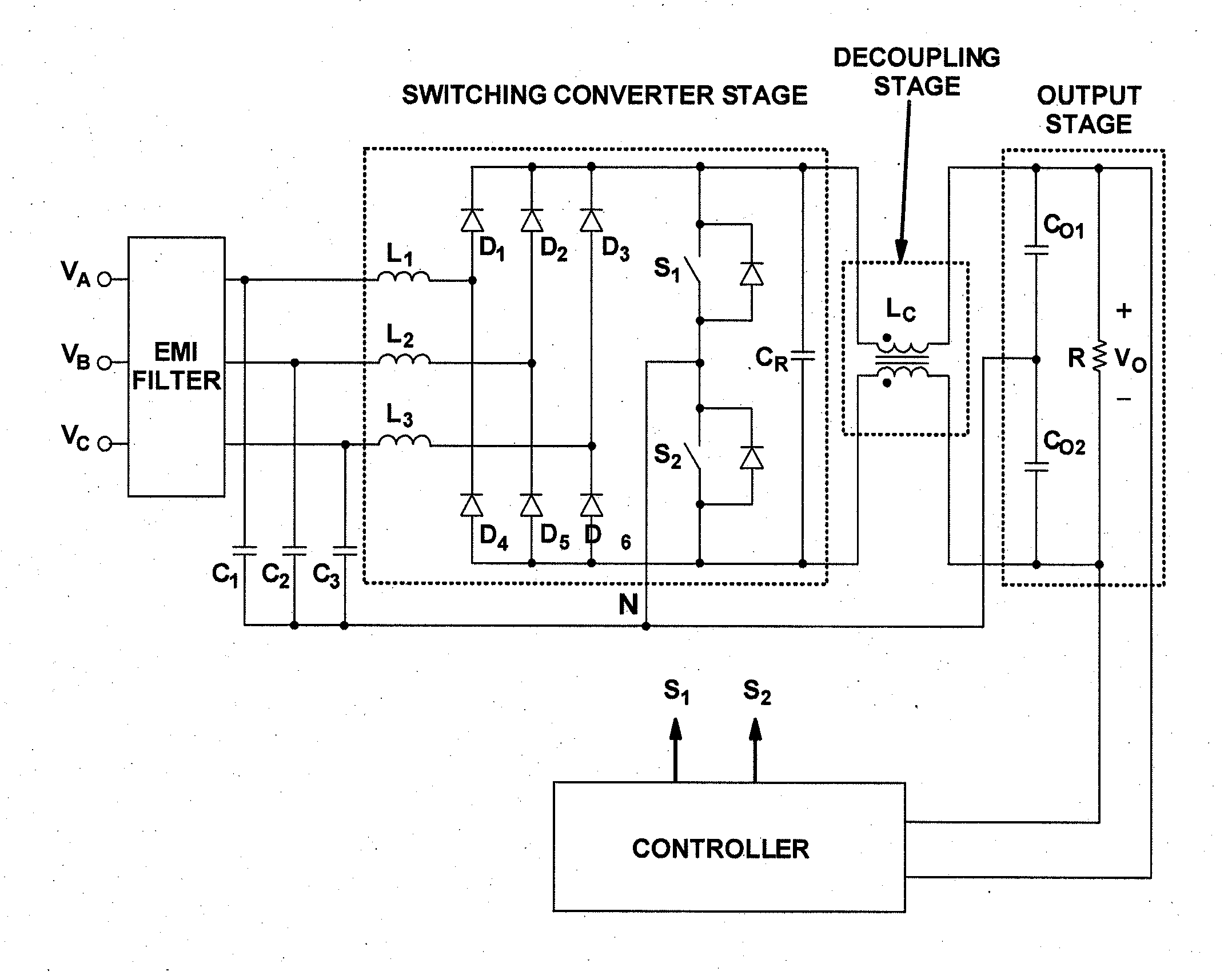
[0073]The present invention relates to three-phase rectifier implementations that offer a low THD of the input currents and high PF along with soft-switching of the switches in a wide load range. Non-isolated and isolated implementations are described below. Non-isolated implementations may offer reduced common-mode noise and automatic balancing of the split capacitors when serially-connected downstream converters are employed. Isolated implementations may provide galvanic isolation of the output from the input side. Moreover, by employing an additional phase-shift or pulse-width-modulation (PWM) control with added switches, the isolated implementations can tightly control their output voltages to minimize unnecessary voltage ripples. Circuits may also be interleaved to reduce their current and voltage ripples.

[0074]FIG. 6 shows a block diagram of a three-phase two-switch ZVS PFC DCM low input-current harmonic boost rectifier according to an embodiment of the present invention. The ...


PUM


Abstract

A low input-current harmonic three-phase boost rectifier includes an input stage for receiving a three-phase input voltage in relation to a neutral node and an output stage adapted to couple to at least one load. The rectifier further includes one or more switching converter stages, each having a plurality of switches coupled to the neutral node, the plurality of switches operating with a fixed duty cycle, the fixed duty cycle being a substantially 50% duty cycle. The rectifier further includes one or more controllers adapted to vary the switching frequency of the plurality of switches based on at least one of a condition of the at least one load or the input voltage and includes one or more decoupling stages, each including one or more inductive elements adapted to inductively decouple the output stage from at least one of the one or more switching converter stages.

Description

FIELD OF THE INVENTION[0001]The present invention generally relates to front-end rectifiers with power-factor correction (PFC) and more particularly to three-phase PFC rectifiers.BACKGROUND[0002]It is well established that three-phase power-factor-correction (PFC) rectifiers with three or more switches exhibit superior power factor (PF) and total harmonic distortion (THD) compared with those implemented with a fewer number of switches that cannot actively shape each phase current independently. However, because of the simplicity and low cost, single and two switch rectifiers are still very attractive for employment in cost-sensitive applications.[0003]FIG. 1 shows the most commonly employed prior art three-phase single-switch rectifier. This simple three-phase boost rectifier performs low-harmonic rectification by operating in the discontinuous-conduction mode (DCM), i.e., by allowing the boost inductors to completely discharge their energies in each switching cycle. As well known, ...

Claims


Application Information

Patent Timeline
Patent Type & Authority Applications(United States)
IPC IPC(8): H02M5/45
CPCY02B70/126H02M1/4216Y02B70/10Y02P80/10
Inventor JANG, YUNGTAEKJOVANOVIC, MILAN
Owner DELTA ELECTRONICS INC
Why Eureka
Try Eureka