Golf ball with RFID system

a radiofrequency identification and golf ball technology, applied in the incorporation of printed electrical components, printed circuits, electrical appliances, etc., can solve the problems of preventing the transmission efficiency of signal energy from dropping, and achieve the effect of reducing the thickness of the antenna, preventing deformation and separation of the antenna, and ensuring the durability of the antenna against an impact from the golf ball

Inactive Publication Date: 2013-08-01
BRIDGESTONE SPORTS
View PDF4 Cites 25 Cited by
  • Summary
  • Abstract
  • Description
  • Claims
  • Application Information

AI Technical Summary

Benefits of technology

[0008]Using conductive ink having excellent heat resistance in formation of the RFID circuit instead of silicon that is conventionally used enables the RFID circuit to be formed as a part of a structure of the golf ball in the manufacturing process of the golf ball. Additionally, the formation of the RFID using conductive ink prevents the RFID circuit from being damaged or separated even when the golf ball is hit, thereby preventing transmission efficiency of signal energy from dropping. Furthermore, use of the conductive ink enables formation of an RFID circuit having a small thickness, and thereby the sphericalness and symmetry of the golf ball can be maintained. By formation of the RFID circuit using conductive ink, freedom in designing or forming the RFID circuit in the structure or manufacturing process of the golf ball can be greatly improved.
[0021]Even if the thickness of the antenna is reduced as a result of forming the antenna by forming the groove in the surface of the intermediate layer and pouring conductive paste into the groove, deformation and separation of the antenna can be prevented upon injection molding of the cover layer. Additionally, durability of the antenna against an impact from the golf ball can be secured sufficiently. Furthermore, because the antenna is formed in the groove, the surface of the intermediate layer can be ground without damaging the antenna and thus, adhesion between the intermediate layer and the cover layer can be secured sufficiently.

Problems solved by technology

Additionally, the formation of the RFID using conductive ink prevents the RFID circuit from being damaged or separated even when the golf ball is hit, thereby preventing transmission efficiency of signal energy from dropping.

Method used


Image

  • Golf ball with RFID system
  • Golf ball with RFID system

Examples


second embodiment

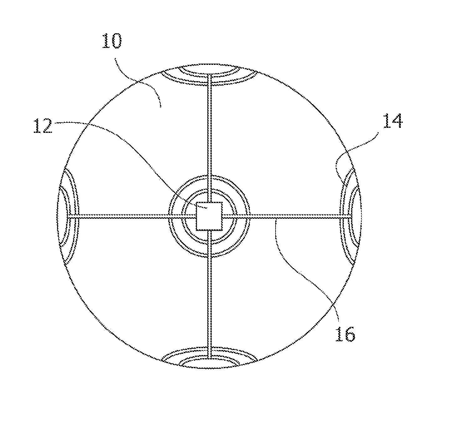
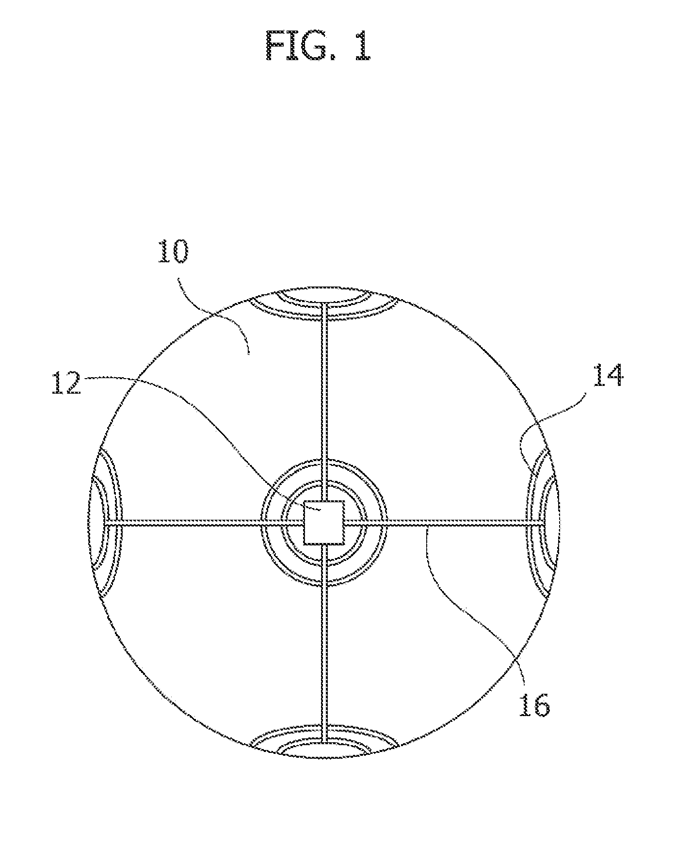
[0030]For example, the golf ball includes a core layer having a groove in its surface, a cover layer which covers the core layer, and an intermediate layer disposed between the core layer and the cover layer. The RFID circuit may be formed of conductive ink within the groove of the core layer. The groove of the core layer is not limited to any particular shape as long as it has a shape suitable for accommodating the RFID circuit and may be quadrangular such as square or rectangular or of other shape. Furthermore, the number of the core layers is not limited to any particular one as long as the groove has a depth sufficient for accommodating the RFID circuit. The RFID circuit may be formed of conductive ink within the groove in the surface of the golf ball using an ink jet printer like the surface of the golf ball.

[0031]In the present invention, the antenna may be formed of conductive ink within the groove in the core layer. The groove for the antenna is not limited to any particula...

third embodiment

[0032] the golf ball includes a core layer, an intermediate layer which covers the core layer and has a groove on its surface and a cover layer which covers the intermediate layer, and the RFID circuit may be formed of conductive ink within the groove of the intermediate layer. The groove of the intermediate layer is not limited to any particular one as long as it has a shape suitable for accommodating the RFID circuit, and may be formed in a predetermined shape like the groove of the core layer. Furthermore, the groove of the intermediate layer is not limited to any particular one as long as it has a depth sufficient for accommodating the RFID circuit.

[0033]In the present embodiment, the antenna may be formed of conductive ink within the groove of the intermediate layer. The groove for the antenna is not limited to any particular one as long as it has a shape suitable for accommodating the antenna, and it may be formed in a predetermined shape like the groove of the core layer. The...


PUM


Abstract

A golf ball has a radio-frequency identification (RFID) circuit for storing ID information therein, the RFID circuit formed of conductive ink; and an antenna for communicating by using radio frequency signals, the antenna connected to the RFID circuit. The antenna may be formed of conductive ink or paste. The RFID circuit and the antenna may be formed on the surface of the golf ball. The golf ball may further include a core layer, a cover layer disposed on the outside of the core layer, and optionally, an intermediate layer disposed between the core layer and the cover layer. The core or intermediate layer has a groove on the surface thereof, and the RFID circuit and the antenna may be formed within the groove.

Description

CROSS-REFERENCE TO RELATED APPLICATIONS[0001]The present invention relates to Provisional Patent Application No. 61 / 592,220, filed on Jan. 30, 2012, which is incorporated herein by reference in its entirety.BACKGROUND OF THE INVENTION[0002]The present invention relates to a golf ball with a radio-frequency identification (RFID) system.[0003]Generally, a RFID tag includes an IC chip made of silicon and an antenna made of metal. Although recently the size of the RFID tag has been decreased considerably, it is not a size which is small enough to be unnoticeable because it has an antenna several centimeters long on a silicon chip 0.4 mm square.[0004]In addition, a problem concerning heat cannot be neglected. This is not a problem concerning a temperature in use on an actual playing field, but a thermal problem in heating process which is necessary for production processes of a variety of related products. In current semiconductors, raw materials do not have sufficient heat resistance. D...

Claims


Application Information

Patent Timeline
Patent Type & Authority Applications(United States)
IPC IPC(8): A63B43/00A63B37/00
CPCA63B43/004A63B37/007A63B37/0003A63B2225/54A63B37/0075A63B2225/15A63B37/0074H05K1/092H05K1/16
Inventor SHIMIZU, TAKUICHIKAI, MASATAKA
Owner BRIDGESTONE SPORTS
Why Eureka
Try Eureka