Device and method for reducing a magnetic unidirectional flux fraction in the core of a transformer

a technology of unidirectional flux and transformer core, which is applied in the direction of magnetic variable regulation, process and machine control, instruments, etc., can solve the problems of affecting the lifetime of winding insulation, asymmetric control of the magnetic material in the core, and electric transformers such as those used in energy distribution networks can be subject to unwanted injection of direct current, so as to reduce the magnetic energy stored in the inductance, the effect of very low expenditure and simple retrofitting

Active Publication Date: 2013-08-08
SIEMENS ENERGY GLOBAL GMBH & CO KG
View PDF2 Cites 15 Cited by
  • Summary
  • Abstract
  • Description
  • Claims
  • Application Information

AI Technical Summary

Benefits of technology

[0021]In a particularly preferred embodiment, the switching unit is controlled such that a pulsating direct current is fed into the compensation winding. This has the advantage that the arithmetic mean value of this pulsating direct current can be predetermined very simply in accordance with the DC component to be compensated. Advantageously, for the purposes of reducing the magnetic energy stored in the inductance, the electronic switching unit remains switched on until the pulsating direct current has decayed. Hence, when the electric switching unit has switched off, an overvoltage protection is required to absorb virtually no residual magnetic energy stored

Problems solved by technology

Electrical transformers, such as those used in energy distribution networks can be subject to the unwanted injection of a direct current into the primary winding or secondary winding.
This results in an asymmetrical control of the magnetic material in the core and is associated with a series of drawbacks.
Even a direct current in the order of a few amperes can cause local heating in the transformer, which can impair the lifetime of the winding insulation.
A further unwanted effect is increased n

Method used


Image

  • Device and method for reducing a magnetic unidirectional flux fraction in the core of a transformer
  • Device and method for reducing a magnetic unidirectional flux fraction in the core of a transformer
  • Device and method for reducing a magnetic unidirectional flux fraction in the core of a transformer

Examples


Embodiment Construction

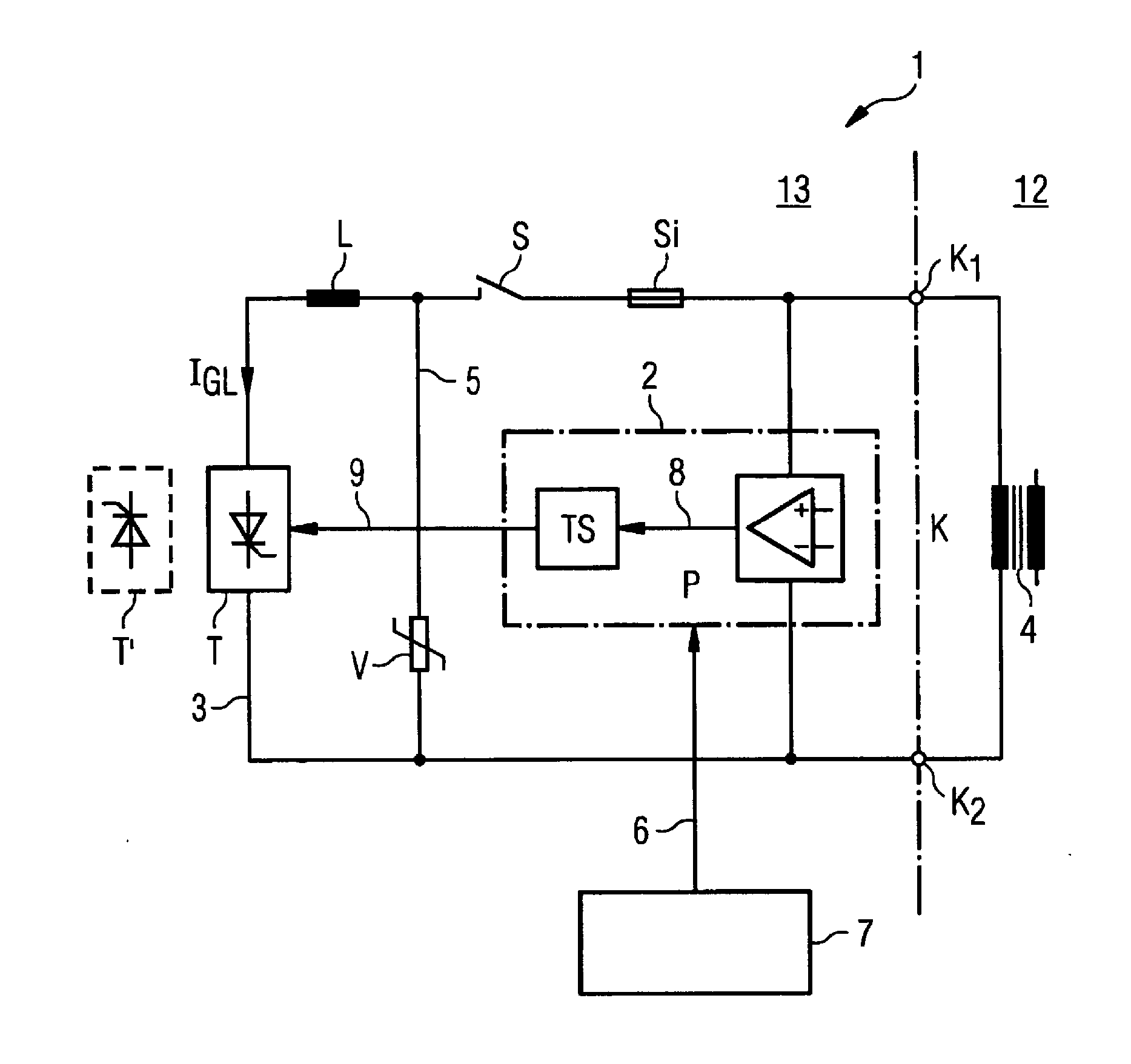
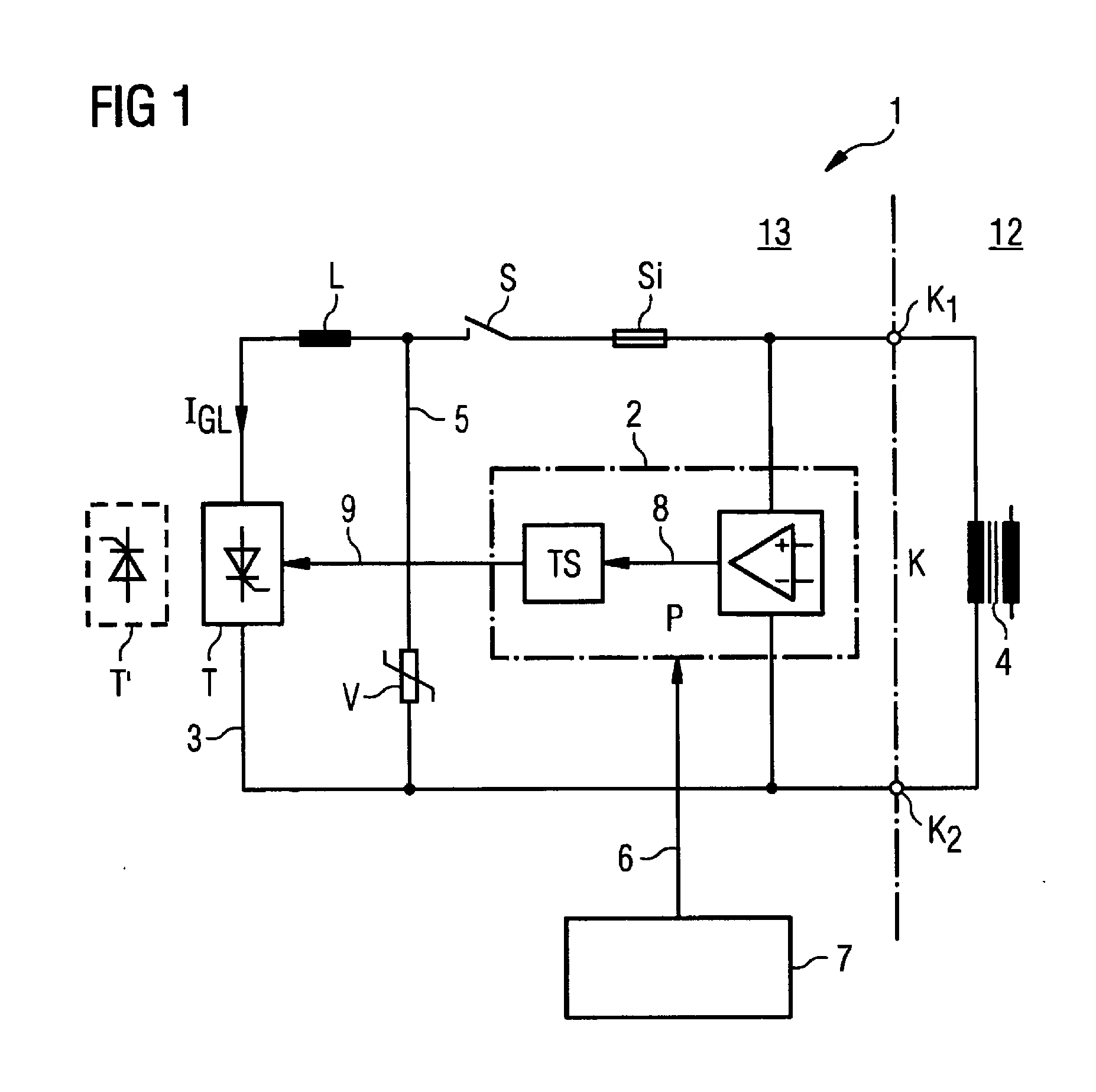
[0027]FIG. 1 shows a device 1 according to an exemplary embodiment of the invention in a simplified depiction. The device 1 substantially comprises a circuit arrangement connected via the terminals K1 and K2 to a compensation winding arrangement K. The compensation winding arrangement K is housed in the transformer tank 12 and magnetically coupled to the core 4 of the transformer. It usually only comprises a winding with a low number of turns, which is, for example, wound around a limb or a yoke part of the transformer. From the compensation winding K in the transformer tank 12, the connections on the terminals K1 and K2 are led out into the outer area 13.

[0028]During the operation of the transformer, an electric voltage is induced in the compensation winding K, said voltage being used according to the invention to combat the disruptive direct component of the magnetic flux in the core 4. This is performed by line-commutated switching of a switching unit T.

[0029]The following explai...


PUM


Abstract

A device for reducing a magnetic unidirectional flux fraction in the core of a transformer is provided. The device has a measuring device that provides a sensor signal corresponding to the magnetic unidirectional flux fraction, a compensation winding that is magnetically coupled to the core of the transformer, a switching unit arranged electrically in a current path in series with the compensation winding in order to feed a current into the compensation winding. The action of the current is directed opposite to the unidirectional flux fraction. The switching unit can be controlled by a regulating variable provided by a control device and can be switched into a conductive state during a predefined time interval and in accordance with the regulating variable, the switch-on time being mains-synchronous. A device for limiting the current in the current path is provided and the sensor signal is fed to the control device.

Description

CROSS REFERENCE TO RELATED APPLICATIONS[0001]This application is the US National Stage of International Application No. PCT / EP2010 / 064397 filed Sep. 29, 2010 and claims the benefit thereof. The application is incorporated by reference herein in its entirety.FIELD OF THE INVENTION[0002]The invention relates to a device and a method for reducing a magnetic unidirectional flux fraction in the core of a transformer with a measuring device, which provides a sensor signal corresponding to the magnetic unidirectional flux fraction, with a compensation winding, which is coupled magnetically to the core of the transformer, with a switching unit, which is arranged electrically in a current path in series with the compensation winding in order to feed a current into the compensation winding, wherein the action of said current is directed opposite to the unidirectional flux fraction, wherein the switching unit can be controlled by means of a regulating variable provided by a control device; the...

Claims


Application Information

Patent Timeline
IPC IPC(8): G05F7/00
CPCH01F27/33H01F27/38G05F7/00H01F2029/143H01F27/42
Inventor HAMBERGER, PETERLEIKERMOSER, ALBERT
Owner SIEMENS ENERGY GLOBAL GMBH & CO KG
Why Eureka
Try Eureka