In-situ formed spinal implant

a spinal implant and incision site technology, applied in the field of spinal fusion or arthrodesis, can solve the problems of increasing patient recovery time, increasing tissue disruption at and around the incision site, etc., and achieves the effects of preventing expulsion, reducing the risk of infection, and increasing heigh

Active Publication Date: 2013-08-08
MILELLA JR MICHAEL J
View PDF3 Cites 48 Cited by
  • Summary
  • Abstract
  • Description
  • Claims
  • Application Information

AI Technical Summary

Benefits of technology

[0007]The above-identified needs are met by the present implant, which is preferably delivered or installed thru a small cannula and deployed percutaneously such that it has greater bone contact area than conventional devices, small frontal area for smaller incisions, omni-directional tooth profiles for preventing expulsion, and an increased height from its pre-deployed state. It is contemplated that th

Problems solved by technology

Conventional spinal repair devices require an open installation procedure, which increases patient recovery times and increases tissue disruption at and around the incision site.
One drawback of c

Method used


Image

  • In-situ formed spinal implant
  • In-situ formed spinal implant
  • In-situ formed spinal implant

Examples


Embodiment Construction

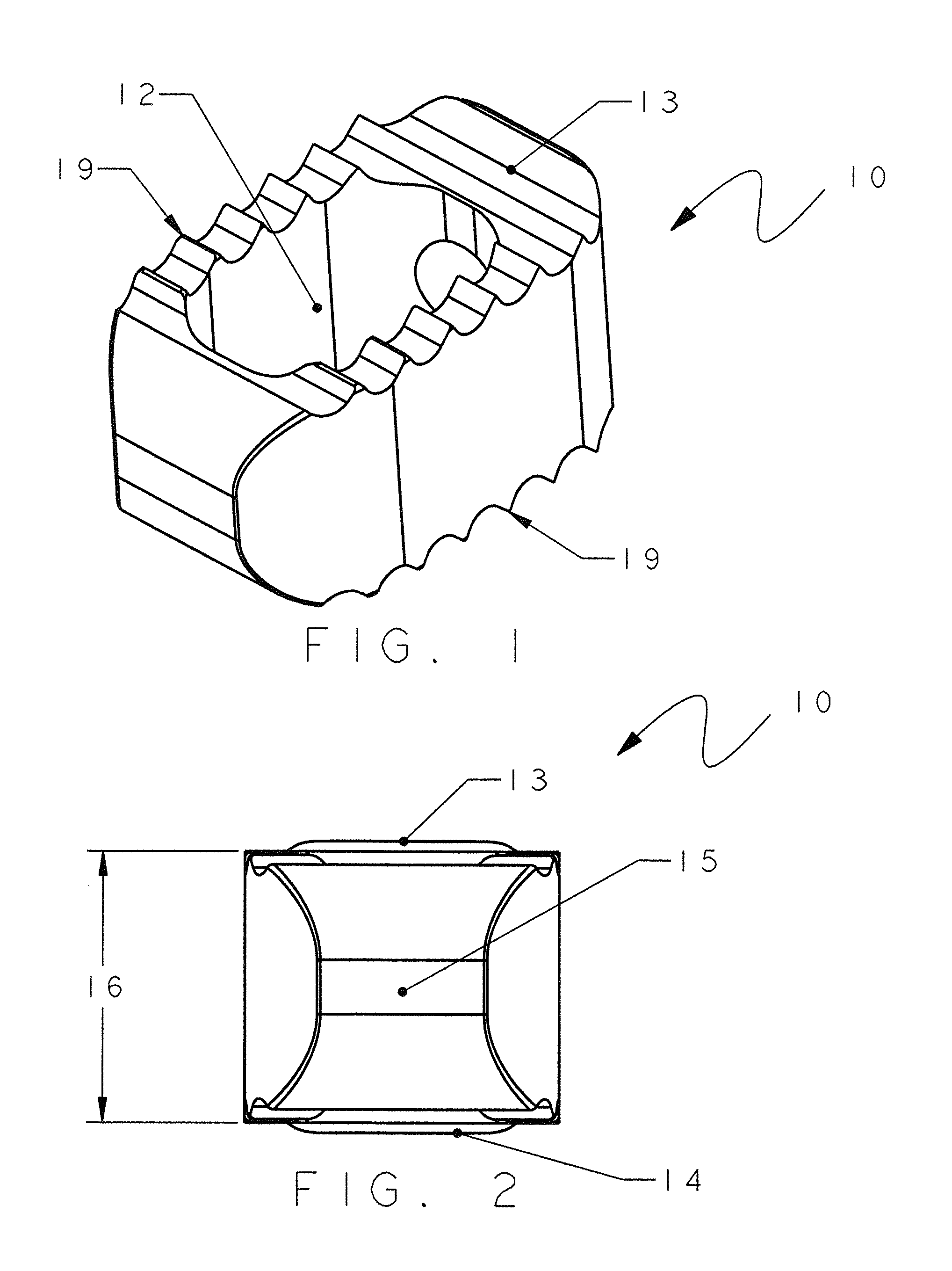
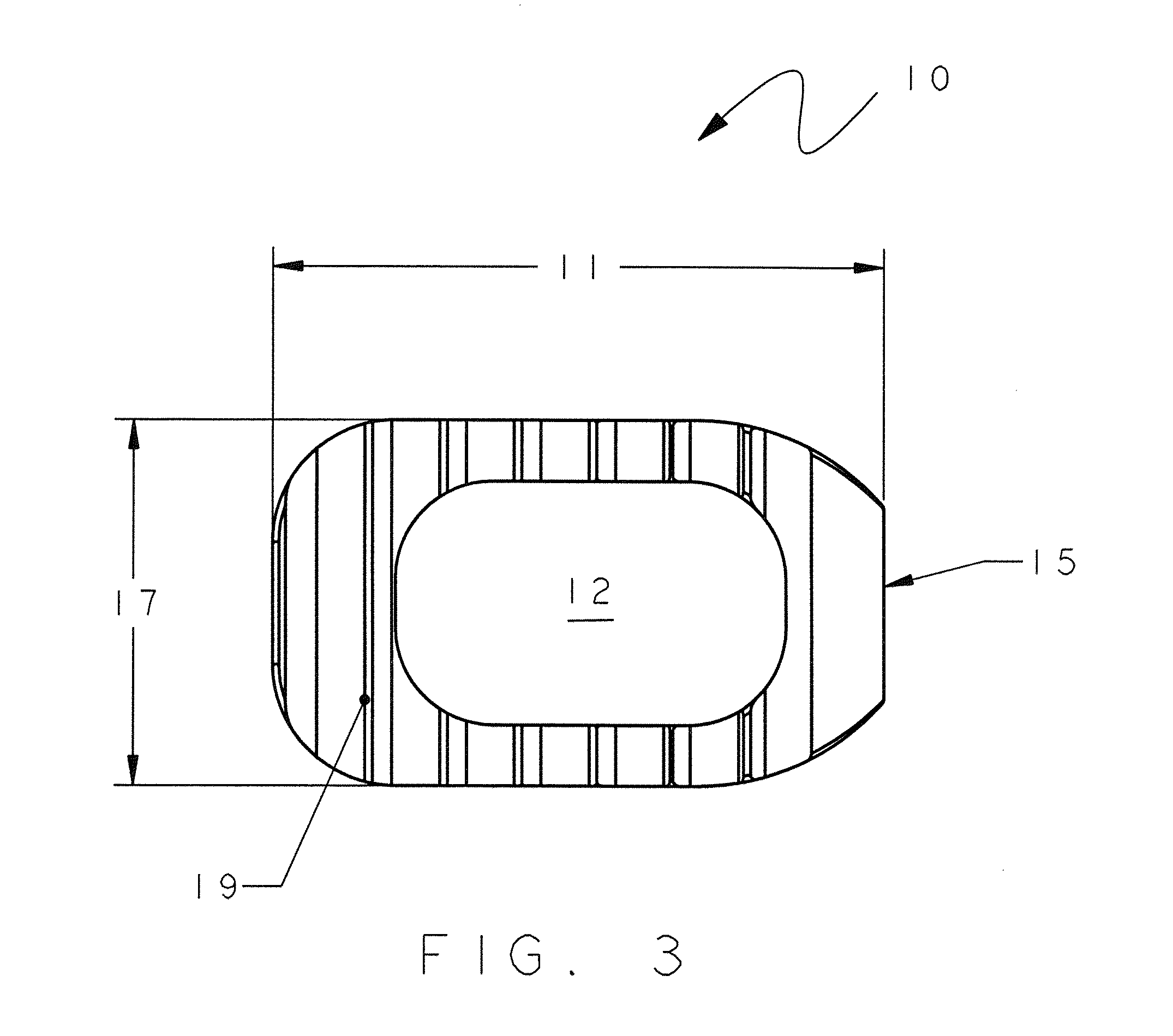
[0061]Referring to FIGS. 1-4A, a prior art implant is shown and generally designated 10, particularly designed for use as in spinal fusion or arthrodesis. However, it is contemplated that the present implant is suitable for use with other types of surgical procedures including, vertebral compression fractures, and as a minimally invasive disc replacement, or the like. The device 10 is preferably machined from bar stock; however other fabrication techniques are contemplated including injection molding. The materials used to manufacture the device 10 include polyetheretherketone (PEEK), titanium alloy, ceramic, bone, carbon fiber, or stainless steel, as is known in the art.

[0062]More specifically, the prior art implant 10 typically includes six sides and an opening defining a passage 12 between upper and lower surfaces, respectively 13 and 14. The passage 12 is generally packed with bone or other natural or artificial materials for use in promoting fusion between an upper and lower ve...


PUM


Abstract

An in-situ formed spinal implant is provided, including an elongate strip having a proximal end and an opposite distal end, the strip having a plurality of spaced teeth disposed along edges of the strip. The strip has a generally arcuate or concave cross-section and is configured for being coiled into a spiral from the proximate end to the distal end for placement between adjacent spinal vertebrae, such that upon formation of the coiled shape, the teeth on a first edge engage one of the vertebrae, and teeth of an opposite, second edge engage the other of the vertebrae.

Description

RELATED APPLICATION[0001]This application claims priority under 35 USC 119(e) from U.S. Provisional Application Ser. No. 61 / 595,091 filed Feb. 5, 2012.BACKGROUND[0002]The present invention relates generally to the field of spinal fusion or arthrodesis, as well as fracture repairs in cases of trauma or osteoporosis, and prosthetic replacement of a spinal joint, particularly relating to installation of a spinal repair device or system of such devices through minimally invasive methods.[0003]Conventional spinal repair devices require an open installation procedure, which increases patient recovery times and increases tissue disruption at and around the incision site. In the case of spinal fusion or arthrodesis, the surgeon typically uses a “cage”, spacer, or an interbody device that distracts the disc space to normal heights. The conventional device aids in fusion of the vertebral bodies by providing an area within the device that can be packed with bone or artificial material creating...

Claims


Application Information

Patent Timeline
IPC IPC(8): A61F2/44
CPCA61F2/4465A61F2/4611A61F2002/2835A61F2002/3008A61F2/442A61F2002/30293A61F2002/30772A61F2002/30841A61F2002/30131A61F2220/0016A61F2230/0069A61F2230/0091
Inventor MILELLA, JR., MICHAEL J.
Owner MILELLA JR MICHAEL J
Why Eureka
Try Eureka