Heat dissipating module

a technology of heat dissipation module and heat dissipation module, which is applied in the direction of tubular elements, lighting and heating apparatus, and semiconductor devices, etc., can solve the problems of limited heat dissipation, damage or affect to electronic elements, and ineffective noise, so as to improve simplify elements. , to achieve the effect of maintaining the working performance of electronic devices and improving the whole heat dissipation efficiency

Inactive Publication Date: 2013-08-15
ASUSTEK COMPUTER INC
View PDF6 Cites 8 Cited by
  • Summary
  • Abstract
  • Description
  • Claims
  • Application Information

AI Technical Summary

Benefits of technology

[0008]A heat dissipating device applied to an electronic device is disclosed. The heat dissipating device simplifies elements in a conventional heat dissipating module, and combines air-cooling with liquid cooling in a limited space to improve the whole heat dissipating efficiency and maintain the working performance of the electronic device effectively.
[0011]The heat dissipating module includes the thermal conductive element and the liquid-pipe in a limited space instead of including only the air-cooling device or the water-cooling device to increase heat dissipating speed greatly. Moreover, the heat dissipating module has more heat dissipating paths, which further improves heat dissipating efficiency.

Problems solved by technology

If the heat is not dissipated instantly, the electronic elements may be damaged or affected.
However, the heat dissipater is limited by the inner height and the weight of the system.
Furthermore, when it is applied to a CPU with a high wattage (such as 130 W or more), a fan with higher rotating speed is needed, the noise is too loud and the heat dissipating efficiency is poor.
However, in a high-level system or electronic device, the heat dissipating effect of air-cooling or liquid cooling is limited due to the device size and the using circumstance.

Method used


Image

  • Heat dissipating module
  • Heat dissipating module
  • Heat dissipating module

Examples


first embodiment

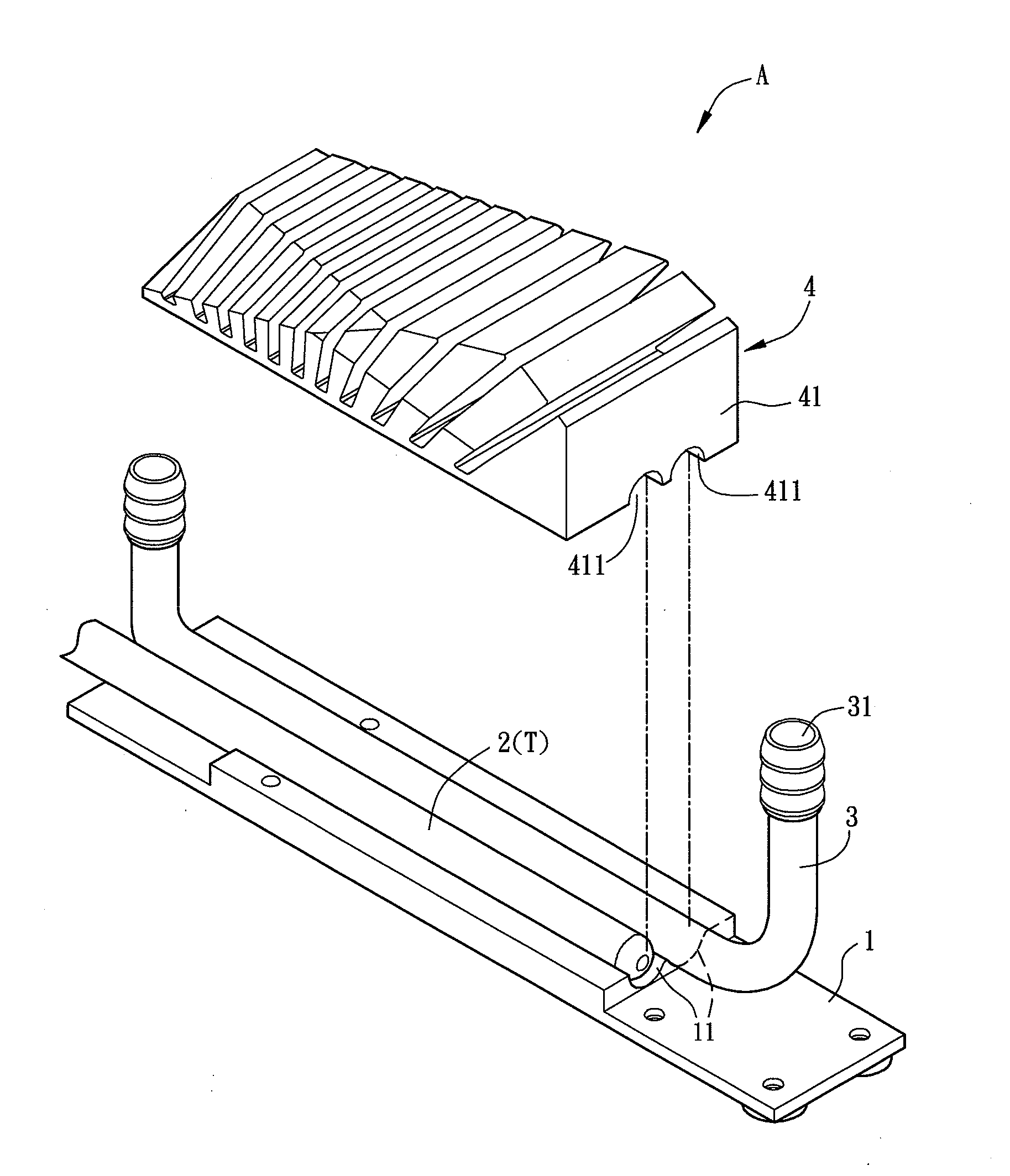
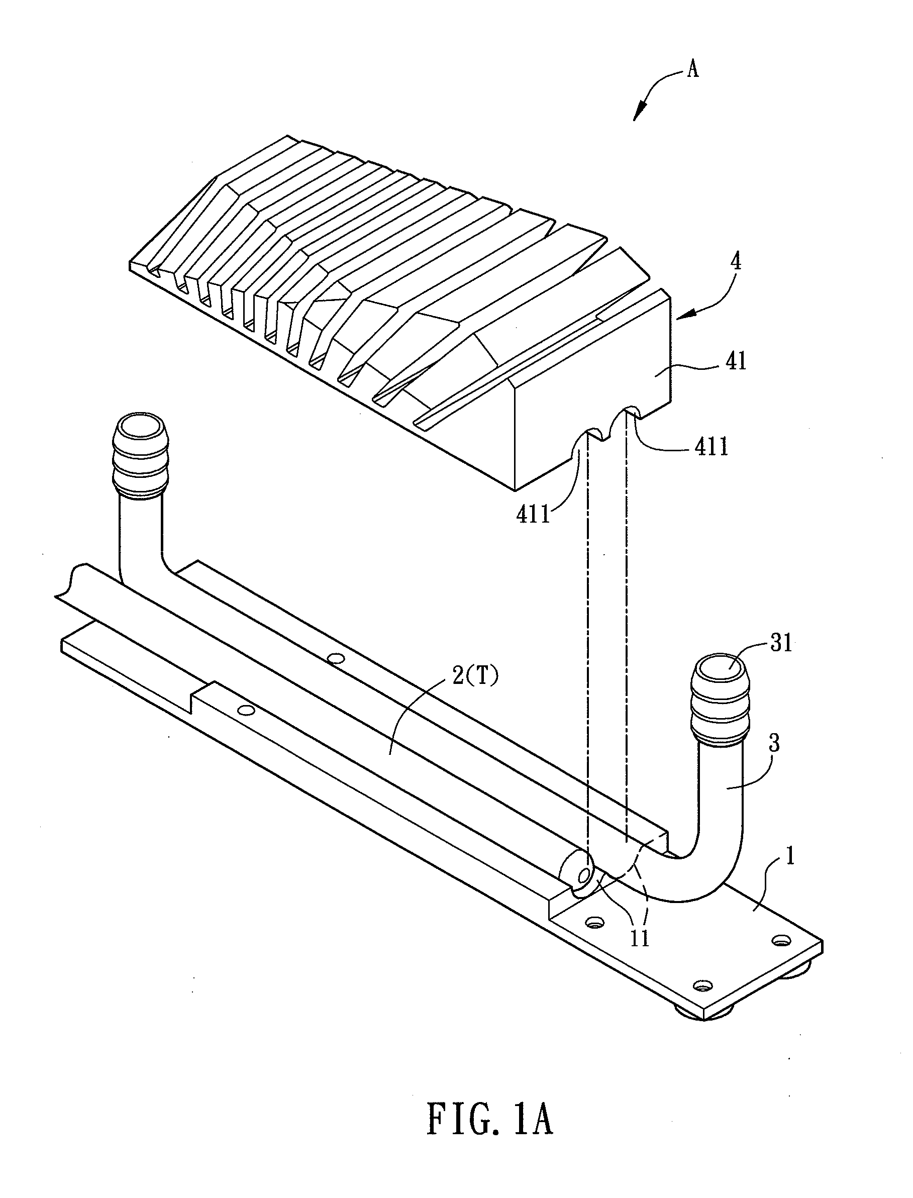
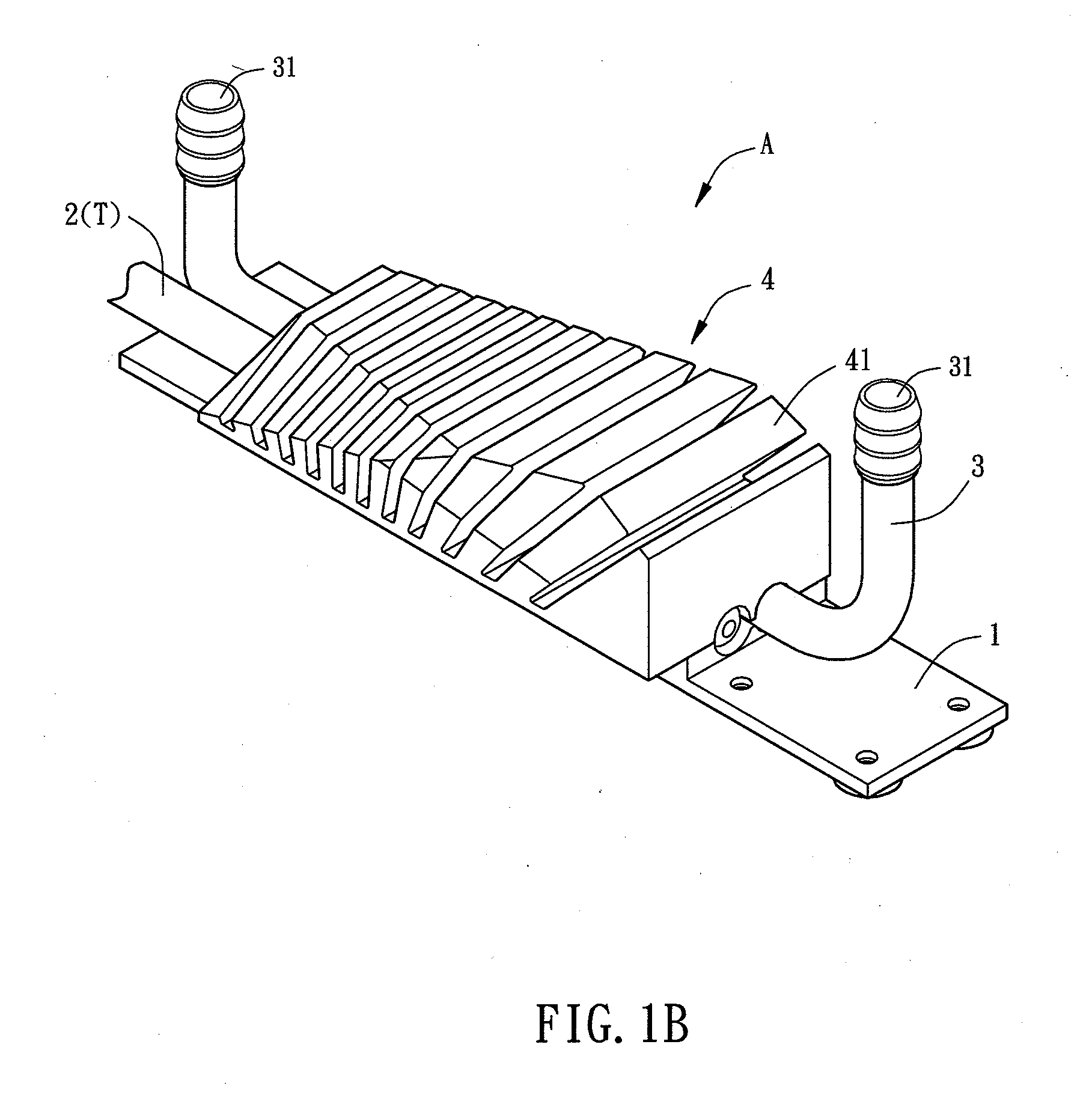
[0024]FIG. 1A is an exploded diagram showing a heat dissipating module in a first embodiment, and FIG. 1B is an schematic diagram showing the assembled heat dissipating module in FIG. 1A. Please refer to FIG. 1A and FIG. 1B, the heat dissipating module A includes a base 1, at least a thermal conductive element T. In the embodiment, the thermal conductive element includes a heat pipe 2, at least a liquid-pipe 3 and a heat sink 4. The heat pipe 2 including the thermal conductive element T is taken as an example. The heat dissipating module A is disposed at a circuit board or other heat sources (such as an electronic element) via the base 1. The structure and components of the heat dissipating module A are illustrated first, and practical usage of the heat dissipating module A with the electronic device would be described later.

[0025]As shown in FIG. 1A and FIG. 1B, the heat pipe 2 and the liquid-pipe 3 are adjacently disposed at a same surface of the base 1. The base 1 may be made of ...

second embodiment

[0038]FIG. 2 is a sectional schematic diagram showing a heat dissipating module in a In the embodiment, the heat dissipating module A′ has similar structures and features with that of the heat dissipating module A, and the difference is that the heat pipe 2′ disposed at the base 1′ contacts with the liquid-pipe 3′. The heat conducting paths from the heat source S to the heat dissipating module A′ are similar to the paths in the above embodiment, and they further include a path L5. Moreover, the heat pipe 2′ is taken as an example of the thermal conductive element T in the embodiment.

[0039]Since the heat pipe 2′ contacts with the liquid-pipe 3′, the heat can be conducted from the heat pipe 2′ to the liquid-pipe 3′ via the path L5 directly, and it does not need to be conducted from the fins 41′ of the heat sink 4′ to the liquid-pipe 3′ via the path L3 and the path L4. Thus, the heat passes through less conducting medium and the heat dissipating path is further shortened, which improv...

third embodiment

[0045]FIG. 4A is an exploded diagram showing a heat dissipating module in a third embodiment, and FIG. 4B is a schematic diagram showing the assembled heat dissipating module in FIG. 4A. As shown in FIG. 4A and FIG. 4B, in the embodiment, the heat dissipating module Al has a similar structure and features with that of the heat dissipating module A in the above embodiment. The difference is that the thermal conductive element includes a thermal conductive sheet 6. The thermal conductive sheet 6 is taken as an example of the thermal conductive element T. The thermal conductive sheet 6 is adjacent to the liquid-pipe 3 and disposed at the base 1a. The heat sink 4a includes a recess 411 and the base 1a includes a recess 11, and the recesses contact with and accommodate the liquid-pipe 3. The heat from the base 1a can be conducted to the fins 41a more evenly via the thermal conductive sheet 6, so as to improve the heat dissipating effect.

[0046]The thermal conductive sheet 6 may be a recta...


PUM


Abstract

A heat dissipating module includes a base, at least one thermal conductive element, at least one liquid-pipe and a heat sink. The thermal conductive element is disposed at the base. The liquid-pipe is disposed adjacent to the thermal conductive element. The liquid-pipe is disposed at the base. The heat sink covers the thermal conductive element and the liquid-pipe. A part of the heat sink is connected to the base. The heat sink includes a plurality of fins. The heat dissipating module combines air-cooling with water-cooling so as to enhance thermal conductivity.

Description

CROSS-REFERENCE TO RELATED APPLICATION[0001]This application claims the priority benefit of U.S. provisional patent application Ser. No. 61 / 597,844, filed on Feb. 13, 2012. The entirety of the above-mentioned patent application is hereby incorporated by reference herein and made a part of specification.BACKGROUND OF THE INVENTION[0002]1. Field of the Invention[0003]The invention relates to a heat dissipating module and, more particularly, to a heat dissipating module combining air-cooling and water-cooling.[0004]2. Description of the Related Art[0005]As execution efficiency and functions of a computer are improved and processing speed enhances, the central processing unit (CPU) or other electronic elements at a motherboard generates more heat due to high frequency oscillation and electromagnetic effect after a long time usage. If the heat is not dissipated instantly, the electronic elements may be damaged or affected.[0006]Conventionally, a heat dissipater is disposed at a heat sour...

Claims


Application Information

Patent Timeline
Patent Type & Authority Applications(United States)
IPC IPC(8): F28F3/02
CPCF28F3/02H01L23/467H01L23/473H01L2924/0002H01L2924/00F28D15/0275F28F1/12
Inventor CHEN, MENG-PINGHO, CHING
Owner ASUSTEK COMPUTER INC
Why Eureka
Try Eureka