
Process for connecting two aircraft fuselage segments by means of friction twist welding

a technology of fuselage and friction twist welding, which is applied in the direction of manufacturing tools, transportation and packaging, other domestic articles, etc., can solve the problems of unsatisfactory flow phenomena, high cost, and high cost of components, and achieve the effect of widening the gap width

Inactive Publication Date: 2013-08-15
AIRBUS OPERATIONS GMBH
View PDF19 Cites 8 Cited by
  • Summary
  • Abstract
  • Description
  • Claims
  • Application Information

AI Technical Summary

Benefits of technology

The invention is a method for connecting two aircraft fuselage segments that can be carried out with a reduced production outlay in terms of the dimensional tolerances, while also permitting a connection with a smooth outer contour of the weld seam. The method allows for greater gap tolerances to be overcome without affecting the weld seam quality and can reduce the dimensional tolerance requirements of the aircraft fuselage segments. The welded region can also be smoothed through a subsequent milling process, resulting in a smooth contour. Additionally, the method allows for a potential for weight reduction and improved strength properties compared to conventional methods. The cover plate used in the method can also function less as a provider of material and more for positioning the material strips in the gap, which results in a lower immersion depth for the welding process.

Problems solved by technology

In the construction of aircraft in particular, the tolerance requirements of the fuselage segments to be connected have not generally previously permitted any butt-joint welding by means of friction twist welding, because the gaps to be expected only permit a process to be carried out with costly additional measures.
The welded interconnection of large components curved in one dimension (i.e. barrel-shaped) requires a tensioning process, in which a substantial part of the tensioning components are inside the components and have to be removed at considerable cost after welding.
The disadvantage of this conventional method is that the components have to be manufactured relatively precisely, as the gap tolerances cannot be greater that approx.
A further disadvantage is that the surface is irregular or rough after the welding process and thus the requirements for a smooth outer skin of the formed aircraft can only be met with increased outlay.
Friction twist welding methods which make use of cover plates are known per se from JP 2004261895 A or EP 1 790 425 A1, but the end surfaces are uneven once the welding process is complete, with the result that the application in the connection of aircraft fuselage segments leads to undesirable flow phenomena at these joint regions.

Method used


Image

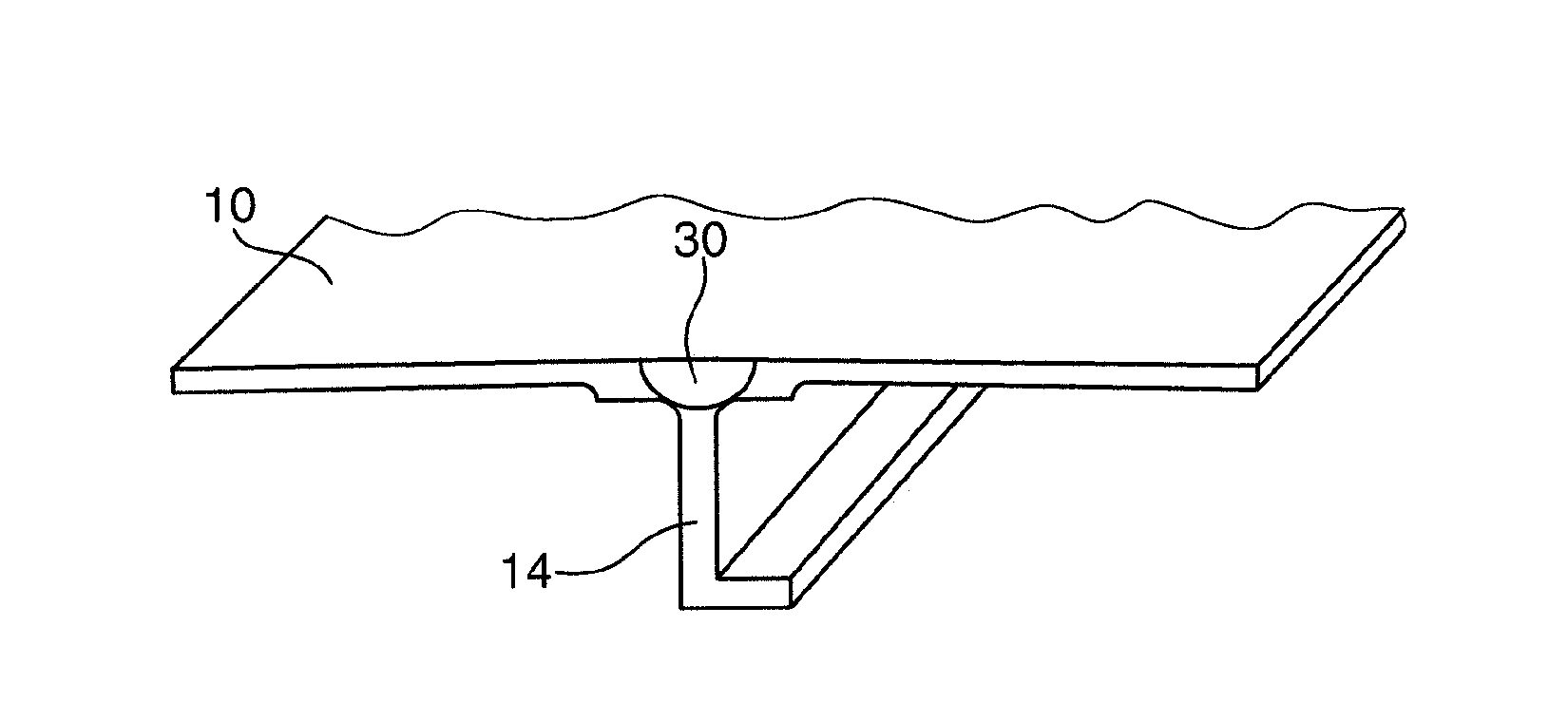
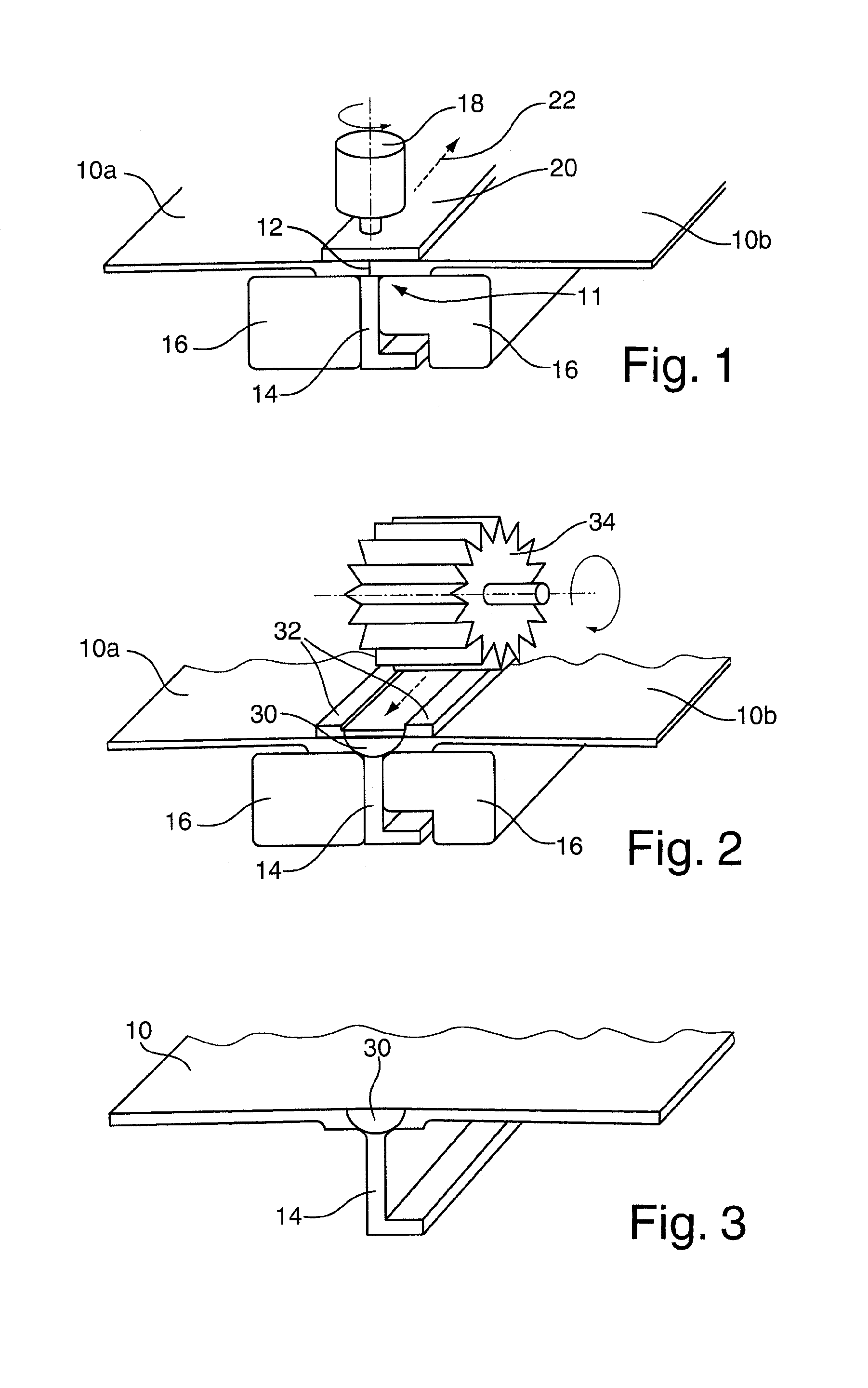
  • Process for connecting two aircraft fuselage segments by means of friction twist welding
  • Process for connecting two aircraft fuselage segments by means of friction twist welding

Examples


Embodiment Construction

[0020]In FIG. 1, two aircraft fuselage segments 10a, 10b are shown in a schematic perspective view, which aircraft fuselage segments comprise two joint regions 11 to be interconnected and meet via these joint regions except for a remaining gap 12.

[0021]A reinforcing profile 14, for example a stringer, is arranged on one side of this gap 12, the connection side of said reinforcing profile lying directly against the region of the gap 12 between the two aircraft fuselage segments 10a, 10b. Two support members 16 are further provided on each side of the reinforcing profile 14 and serve as a thrust bearing for a tool 18 and also guide and fix the reinforcing profile 14 during the welding process.

[0022]Opposite the reinforcing profile 14, the gap 12 is covered by a cover plate 20 which is arranged centrally above the gap 12. In order to carry out the friction twist welding process, the tool 18 rotates (with a rotational speed of approximately 500-2000 1 / min) and is pressed with considerab...


PUM

PropertyMeasurementUnit
thicknessaaaaaaaaaa
thickaaaaaaaaaa
depthaaaaaaaaaa

Abstract

A process for connecting two aircraft fuselage segments and a reinforcing profile arranged in the joint region of the two aircraft fuselage segments by friction twist welding using a rotating tool, wherein a cover plate is brought onto the aircraft fuselage segments to be connected above the joint regions and after the friction twist welding the remainder of the cover plate is milled off. This makes it possible to overcome significantly greater gap tolerances in the edges to be connected so that the dimension tolerance requirements for the aircraft fuselage segments can be reduced. Furthermore, a smooth surface can be achieved in the welding region.

Description

CROSS-REFERENCE TO RELATED APPLICATIONS[0001]This application is a continuation of and claims priority to PCT / EP2011 / 062690 filed Jul. 22, 2011 which claims the benefit of and priority to German Patent Application No. 10 2010 032 402.7 filed Jul. 27, 2010, the entire disclosures of which are herein incorporated by reference.FIELD OF THE INVENTION[0002]The invention relates to a method for connecting two aircraft fuselage segments and a reinforcing profile arranged in the joint region of the two aircraft fuselage segments by friction twist welding using a rotating tool.BACKGROUND OF THE INVENTION[0003]In the construction of aircraft in particular, the tolerance requirements of the fuselage segments to be connected have not generally previously permitted any butt-joint welding by means of friction twist welding, because the gaps to be expected only permit a process to be carried out with costly additional measures. The welded interconnection of large components curved in one dimension...

Claims


Application Information

Patent Timeline
Patent Type & Authority Applications(United States)
IPC IPC(8): B23K20/12
CPCB23K20/122B23K20/128B23K20/129B23K2203/10B64C1/068B23K2201/045B23K2101/045B23K2103/10
Inventor SILVANUS, JUERGENPACCHIONE, MARCOELZE, STEFAN
Owner AIRBUS OPERATIONS GMBH
Learn More