
Bolt

a technology of bolts and bolts, applied in the direction of bolts, nuts, screws, etc., to achieve the effect of reducing material use, reducing time, and facilitating erecting of buildings and structures

Active Publication Date: 2013-08-15
DOYE MARK +1
View PDF10 Cites 7 Cited by
  • Summary
  • Abstract
  • Description
  • Claims
  • Application Information

AI Technical Summary

Benefits of technology

The present invention has several benefits. Firstly, it can securely hold timber together with fewer parts and in less time, reducing the amount of material needed. Secondly, the bolt does not rotate while the nut is tightened, ensuring stability. Lastly, once the bolt is placed in position, it does not fall out and is self-securing, making it easier for a single person to build structures.

Problems solved by technology

The use of a ‘coach bolt’ in securing timber members has many drawbacks and limitations, namely:1. It relies on the user to drill the correctly sized hole through the timber members.
Control Officers to request the use of a 50 mm×50 mm washer.3. It is a common occurrence for the bolt to turn within the timber before it is completely tight or has reached the correct torque.4. It is also a common occurrence for the small head of the bolt to be pulled into the timber member, deforming the timber face, thereby reducing the effective structural depth of the timber as designed.5. In the case of domed headed bolts the bolt makes it difficult to subsequently attach or fix finishing materials, such a plywood and plasterboard, as it is not possible to achieve a true level surface without remedial works being required.6. There are instances which require the contractor to pass the bolt through the first member and then offer up the second member over the bolt.
The second member pushes the bolt out of the first member adding to the frustration.7. Due to the small surface area of the head to the bolt, it is difficult to achieve the correct torque to the nut without deforming the surface of the timber member.
This is a particular issue when the head of the bolt is visible.
It leads to an unsightly finish.8. There is no facility to restrain the bolt in position.
The use of threaded rod in securing timber members also has many drawbacks and limitations, namely:1. Wastage is excessive and common due to the bars being supplied in set lengths.
It is exceptionally unusual to use the entire rod.2. When the rod has been cut, the thread becomes deformed making it difficult to thread the nuts.3. In order to fix the rod in position, it requires two sets of nuts and two sets 50 mm×50 mm washers, which adds expense and is often awkward.4. It is a common occurrence that when tightening one nut, the shaft or bar has a tendency to turn within the opposing nut, thereby winding the rod through the timber members.5. There is no facility to restrain the nut or threaded rod in position.6. It is an awkward and time-consuming activity for those working in construction, as they must tighten one washer and nut onto one side of the threaded rod, then hold it in place with a spanner whilst tightening a washer and nut on the other side resulting in continuous access being required. to both ends of the bolt, using two separate spanners, in order to secure the fixing.
Space constraints commonly experienced on construction sites often restrict the possibility of achieving this.7. The nuts can become loose and may be lost, decreasing the likelihood of the fabrication staying together and potentially putting people at risk.
However, the matter of the head of the bolt gouging into a work piece was not addressed.
The result was that despite a washer and nut being placed on a ‘blind side’, the bolt could still work loose.
As such, in many situations, the screw device does not always meet building regulation standards.

Method used


Image

  • Bolt
  • Bolt
  • Bolt

Examples


Embodiment Construction

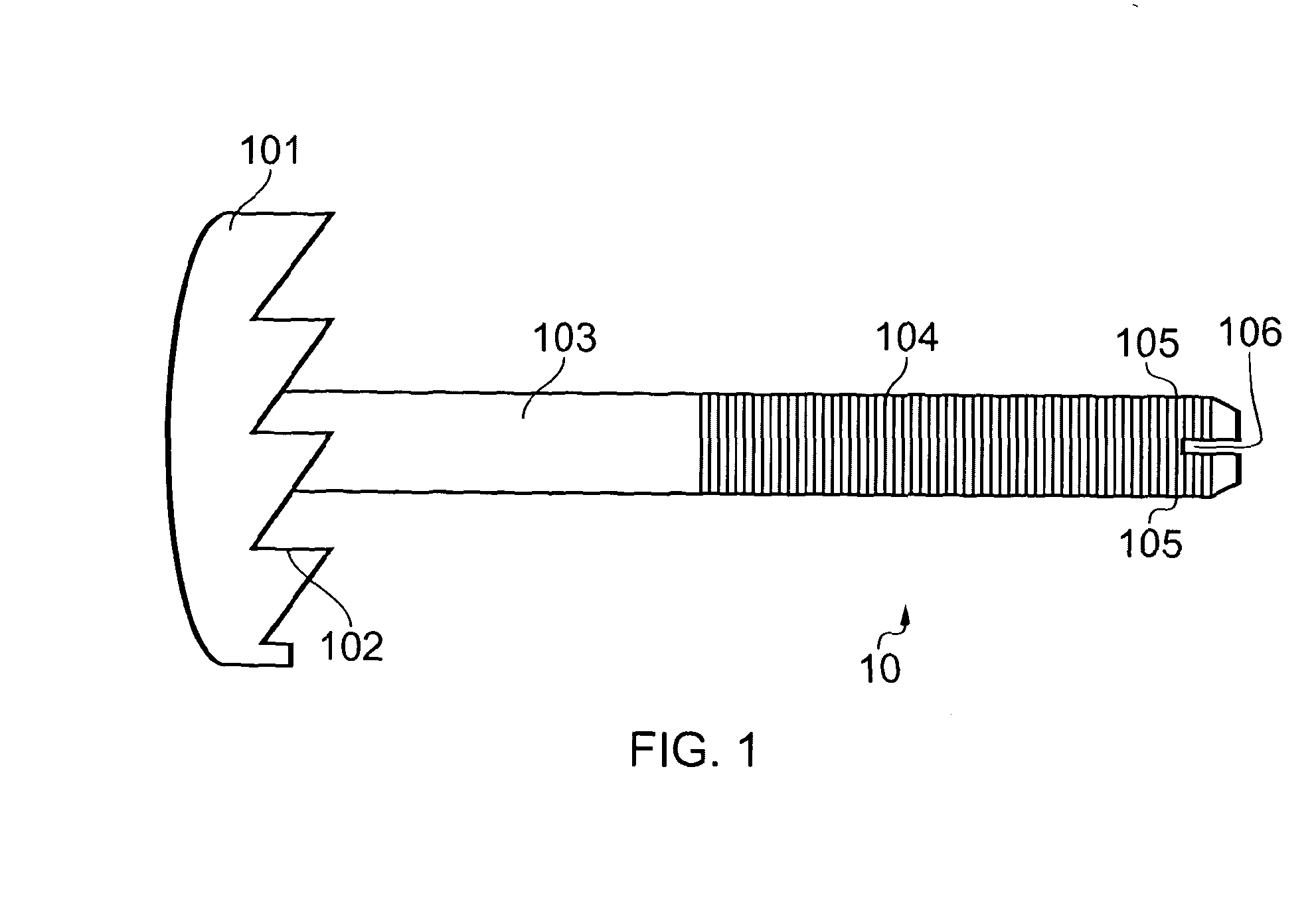
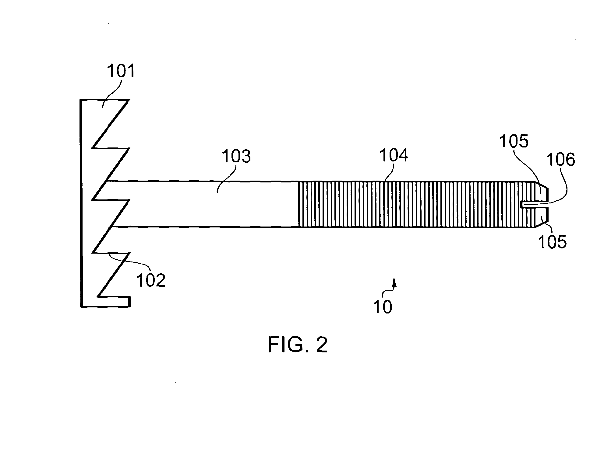
[0067]Referring to the Figures generally and specifically FIGS. 1 and 2 which show a bolt 10, suitable for securing timber. Bolt 10 comprises a bolt head 101 with a series of spiked engagement means, in the form of teeth 102 on its underside. A cylindrical bolt rod 103 extends from the bolt head 101. A portion of the shaft of the bolt rod 103 has a thread 104 formed thereon. The end of the bolt rod 103 is split into two portions 105a and 105b at its free end, defining a slot 106 between the two portions 105a and 105b.

[0068]Bolt head 101 may be of any known bolt head form, for example, it may be a pan head, a domed head, a round head, a truss head or any other, but is ideally square shaped. The bolt head 101 includes a plurality of spiked teeth 102 on its underside, which, in use, contact a work piece to be secured. Spikes 102 are sufficiently sharp to pierce the timber and thus grip onto it.

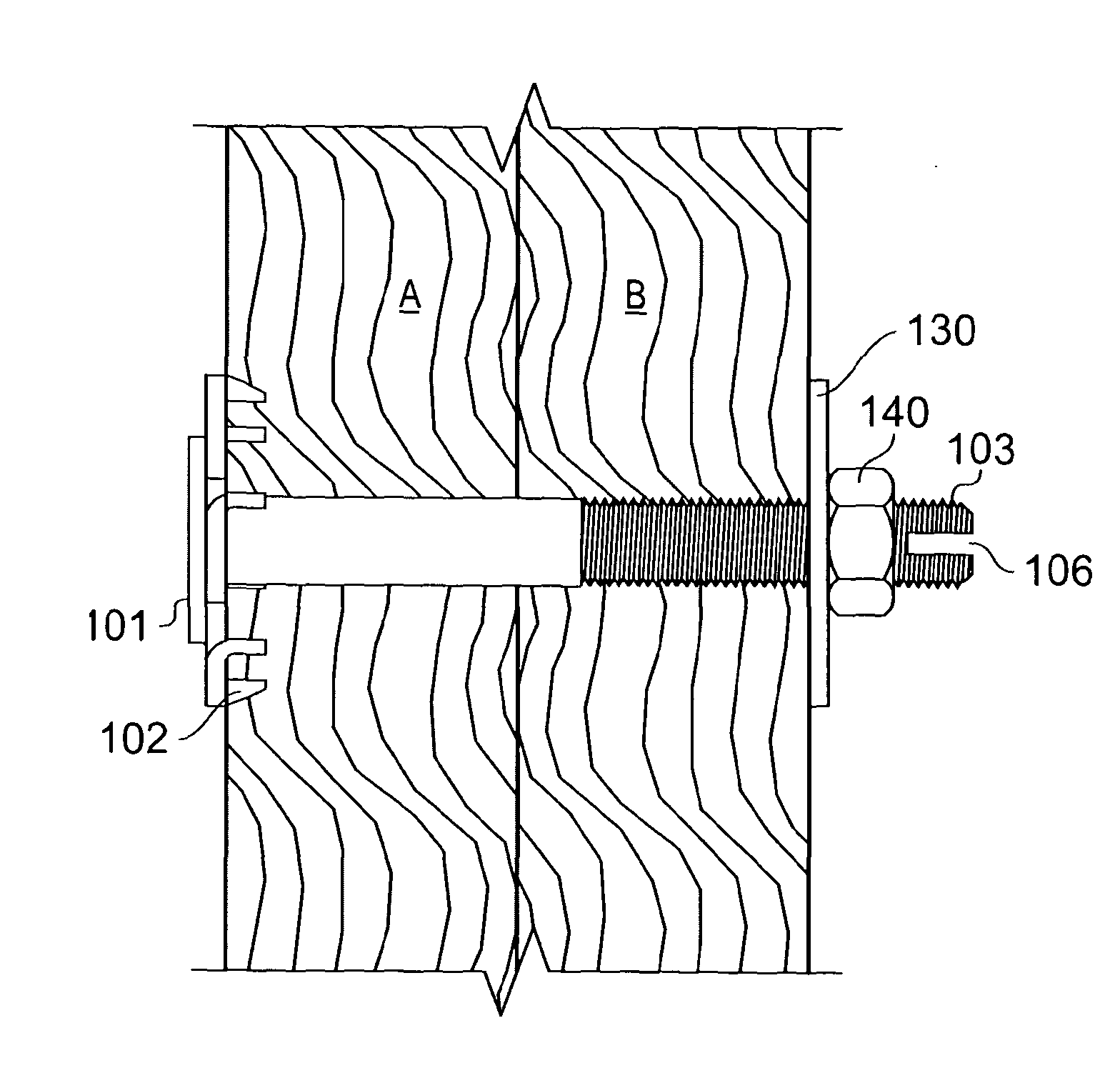
[0069]FIG. 3 shows in diagrammatical form the bolt holding two pieces of wood A and B togeth...


PUM

PropertyMeasurementUnit
Lengthaaaaaaaaaa
Lengthaaaaaaaaaa
Lengthaaaaaaaaaa

Abstract

A bolt (10) for securing timber to any other material, comprises: a bolt head (101) with a series of spiked teeth (102) on its underside; a cylindrical bolt rod (103) extending from the bolt head (101) is threaded and split into two rods (105a,b) at its free end, so as to define a slot (106) therebetween. In use a user drills a hole through pieces of timber to be secured together, and hammers the bolt through the hole. The spiked teeth on the bolt head lock into the timber, securing the bolt at one end. At the free, split end of the bolt rod, a washer and nut are tightened onto the bolt. A cold chisel is hammered into the slot between the split ends of the rod, bending the ends outwards and thus preventing the nut from loosening.

Description

FIELD OF THE INVENTION[0001]The present invention relates to an engineered bolt and more particularly, but not exclusively, the invention relates to an engineered bolt for securing pieces of timber together or pieces of timber to other materials.BACKGROUND OF THE INVENTION[0002]Often, those working in the construction industry, such as builders and carpenters, need to construct prefabricated items or structures from wood or timber. Pieces of wood or timber forming such items or structures were often secured one to another using fixings such as nails, screws or bolts.[0003]Whilst screws and nails were useful for attaching small pieces of wood, one to another, the usual manner of securing larger pieces of timber together or securing timber to third party materials, for example of the sort used in frames and larger structures, involves drilling a hole through each material where they should be joined. There are then two traditional methods of securing the materials together:[0004]Optio...

Claims


Application Information

Patent Timeline
IPC IPC(8): F16B39/02B21J5/00F16B35/06
CPCF16B33/002F16B35/065F16B39/023Y10S411/957B21J5/00F16B35/06F16B39/02F16B43/00F16B35/04F16B35/044F16B33/06F16B39/282
Inventor DOYE, MARKHARDINGHAM, DANIEL
Owner DOYE MARK
Learn More