Integrated pet/mri scanner

a scanner and integrated technology, applied in tomography, instruments, applications, etc., can solve the problems of deteriorating pet performance and not negligible ct exposure, and achieve the effect of improving pet sensitivity without sacrificing mri performance, reducing gaps between pet detectors, and improving sensitivity

Active Publication Date: 2013-08-15
HAMAMATSU PHOTONICS KK +1
View PDF8 Cites 20 Cited by
  • Summary
  • Abstract
  • Description
  • Claims
  • Application Information

AI Technical Summary

Benefits of technology

[0038]According to the present invention, at least transmitting coil elements are disposed between PET detectors. The scintillators of the PET detectors can thus be placed closer to the measuring object without being interfered with the transmitting coil elements which are preferably located away from the measuring object. Thus, the PET sensitivity can be improved without sacrificing the MRI performance.
[0039]In particular, suppose that the PET detectors are composed of a combination of a scintillator that senses radiation and emits light and a light receiving element that senses the light emitted from the scintillator and converts the light into an electrical signal, and the scintillators are located further in the measuring port than the light receiving elements. In such a case, a radio wave shield for allowing the use of the PET detector in the measuring port of the MRI scanner is disposed between the scintillator and the light receiving element except for the outer periphery of the scintillator. The radio wave shields are located further in the measuring port than the ends of the transmitting coil elements of the RF coil for MRI on the inner side of the measuring port. The ends of the scintillators on the inner side of the measuring port are protruded further into the measuring port than the transmitting coils as far as not beyond receiving coils. Consequently, the scintillators can be placed as close to the measuring object as possible to reduce gaps between the PET detectors accordingly, with a further improvement in sensitivity without affecting MRI.
[0040]Moreover, DOI (Depth of Interaction) type detectors (see Patent Literatures 5 and 6) capable of detecting position in a depth direction can be used as the PET detectors for even higher resolution.

Problems solved by technology

However, since X-ray CT typically has an exposure level several times higher than that of PET, CT exposure is not negligible.
Such approaches deteriorate the PET performance because of attenuation of the scintillation light.

Method used


Image

  • Integrated pet/mri scanner
  • Integrated pet/mri scanner
  • Integrated pet/mri scanner

Examples


first embodiment

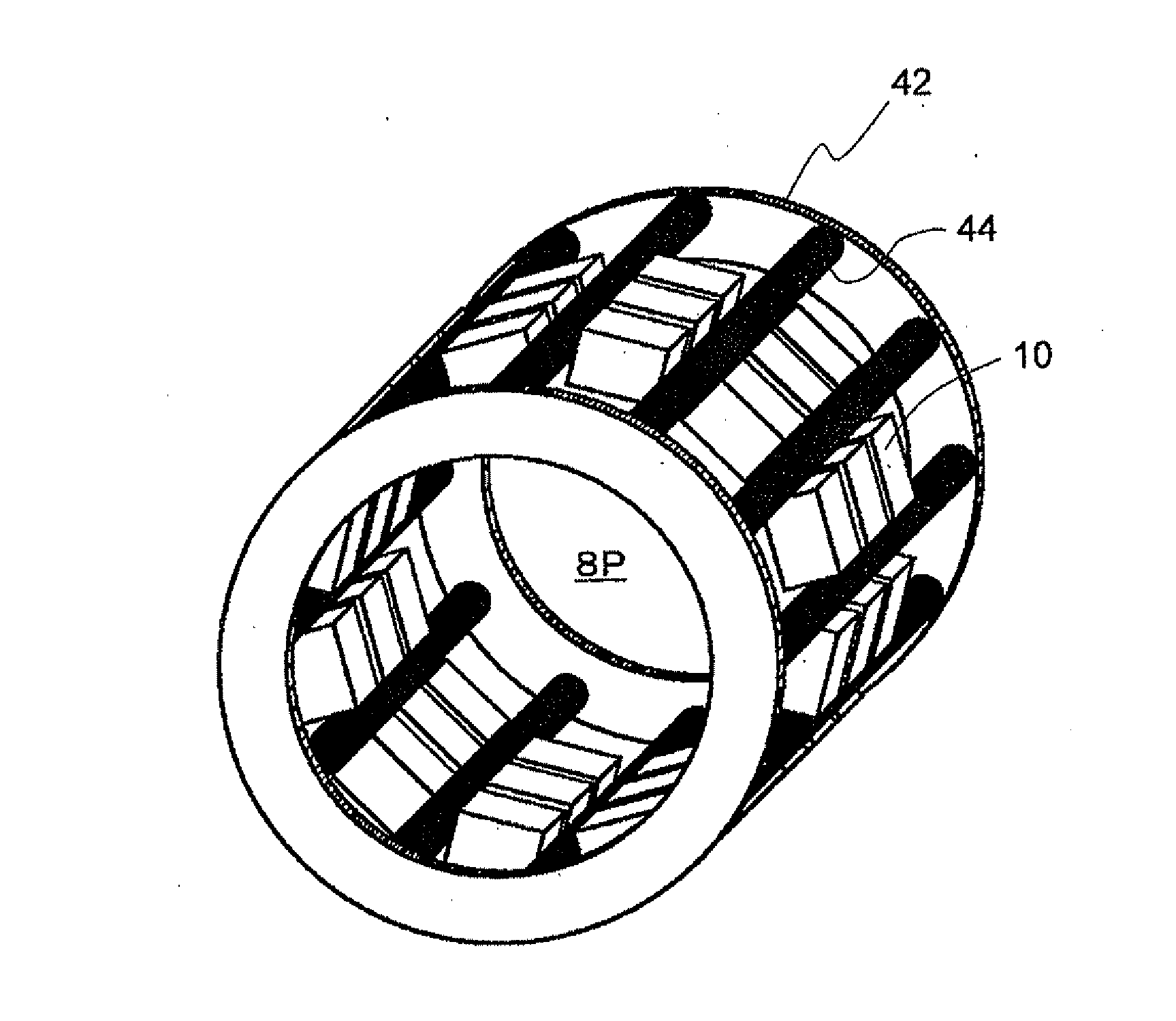
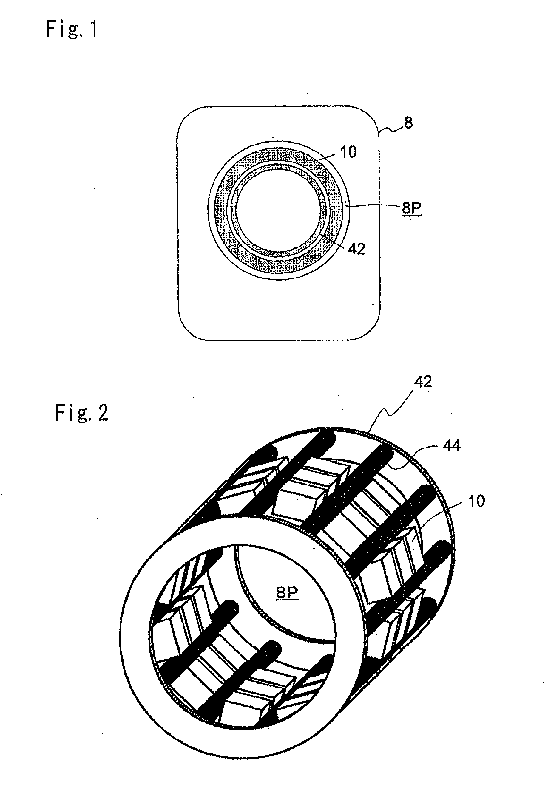
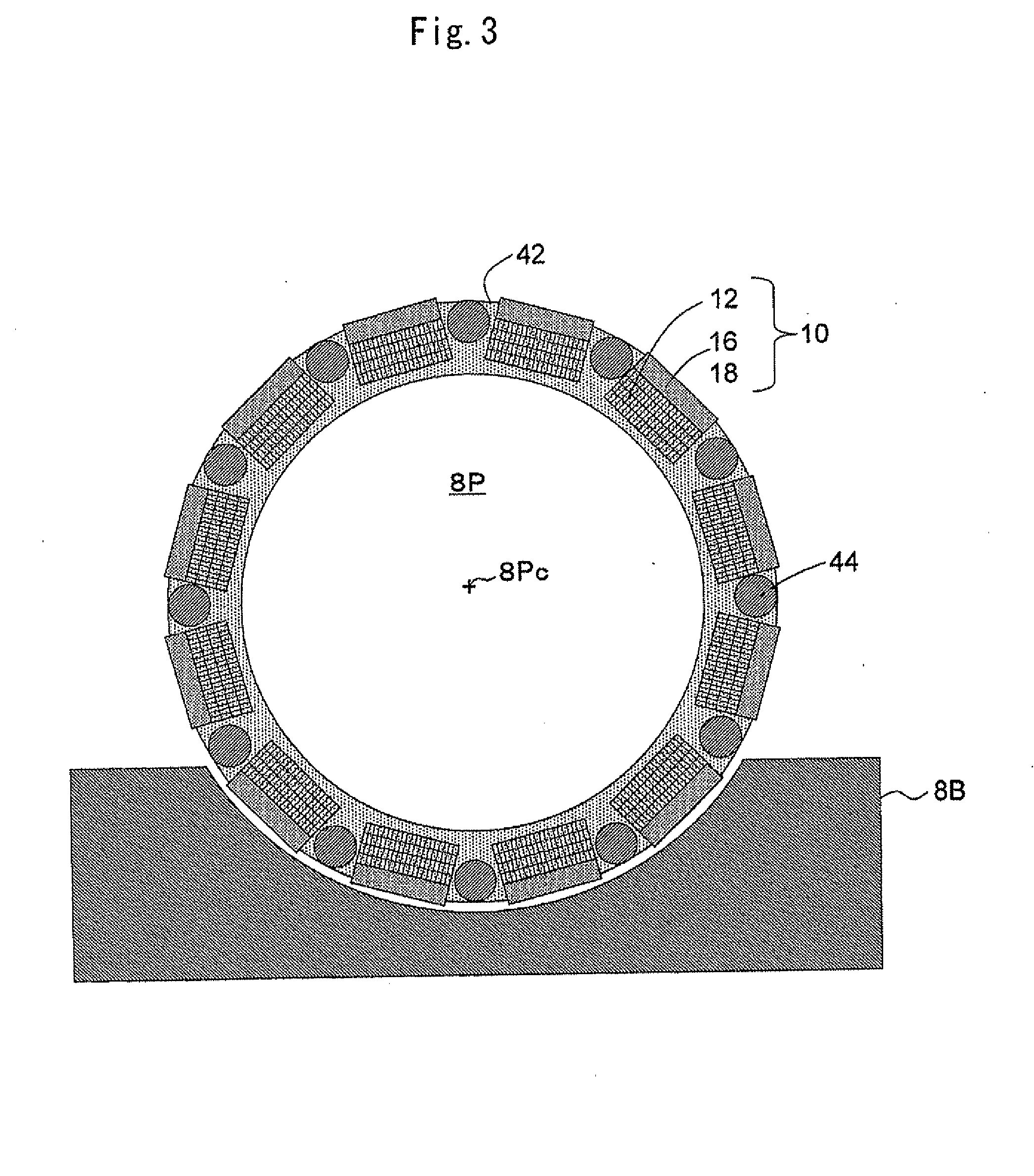
[0069]As shown in FIG. 2 (a perspective view showing the configuration of essential parts) and FIG. 3 (transverse cross-sectional view), the present invention is a transmitting and receiving RF coil (hereinafter, also referred to simply as an RF coil) 42 of so-called birdcage type for head MRI examination. Transmitting and receiving coil elements (hereinafter, also referred to simply as coil elements) 44 contained in bar-shaped cases extending in the axial direction of a measuring port 8P are arranged in parallel, with spaces therebetween. A large number of PET detectors 10 are disposed with spaces therebetween in the circumferential direction of the measuring port 8P. The respective transmitting and receiving coil elements 44 are configured to be contained in the spaces between the PET detectors 10.

[0070]As shown in FIG. 3, the PET detectors 10 are composed of a combination of a light receiving element 16 and a scintillator 12. The scintillator 12 is located further in the measurin...

second embodiment

[0082]FIG. 13 shows the configuration of the integrated PET / MRI scanner according to the present invention, using the PET detector accompanied by a light guide shown in FIG. 11. The light guides 30 are formed in a trapezoidal shape that is larger on the scintillator 12 side, so that scintillators 12 larger than the light receiving areas of the light receiving elements 16 can be connected. The scintillators 12 can also be placed closer to the measuring object as much as the light guides 30 are attached. This can increase the PET sensitivity.

third embodiment

[0083]As in the configuration of a third embodiment shown in FIG. 14, thick light guides 30 can be used to reduce the gaps between the scintillators 12 and place the scintillators 12 closer to the measuring object for increased PET sensitivity, without configuring the light guides 30 into a trapezoidal shape.

[0084]In any of the foregoing first, second, and third embodiments, the coil elements 44 of the RF col 42 are contained in bar-shaped cases. As in a fourth embodiment shown in FIG. 15, the coil elements 44 may be contained, for example, in plate-shaped cases that are wide in the circumferential direction of the measuring port 8P.


PUM


Abstract

In the integrated PET/MRI scanner provided with an RF coil for MRI and a plurality of PET detectors in the measuring port of the MRI scanner, the PET detectors are disposed with spaces therebetween and at least the transmitting coil elements of the RF coil for MRI are disposed between adjacent PET detectors. Here, the PET detectors are disposed in the circumferential direction of the measuring port with spaces therebetween and the transmitting coil elements are disposed in the axial direction of the measuring port. Alternatively, at least some of the PET detectors are disposed in the axial direction of the measuring port with spaces therebetween and the transmitting coil elements are disposed between adjacent PET detectors. The PET detectors can be DOI-type detectors capable of detecting position in the depth direction.

Description

TECHNICAL FIELD[0001]The present invention relates to an integrated PET / MRI scanner that integrates a PET (Positron Emission Tomography) scanner and an MRI (Magnetic Resonance Imaging) scanner, and more particularly to an integrated PET / MRI scanner in which PET detectors can be placed close to a measuring object to increase the sensitivity and spatial resolution of PET.BACKGROUND ART[0002]PET is a method of administering a compound that is labeled with positron-emitting radionuclides and imaging the distribution of the compound in the body as a tomographic image by processing data obtained by PET detectors including combinations of light receiving elements and scintillators, or CdTe, CZT, or other semiconductor detectors. While X-ray CT (Computed Tomography) and MRI based tomographic images provide anatomical information, PET images are referred to as functional images which express biological functional information. For example, PET images are capable of highly sensitive tumor dete...

Claims


Application Information

Patent Timeline
Patent Type & Authority Applications(United States)
IPC IPC(8): A61B6/00A61B5/055A61B6/03
CPCA61B5/055A61B6/037A61B6/4258A61B6/4417G01R33/481A61B6/5247G01T1/1603G01R33/34076A61B6/501A61B5/0035
Inventor YAMAYA, TAIGANISHIKIDO, FUMIHIKOOBATA, TAKAYUKISUGA, MIKIOSAITO, KAZUYUKIWATANABE, MITSUOTANAKA, EIICHI
Owner HAMAMATSU PHOTONICS KK
Why Eureka
Try Eureka