Roller tappet

Active Publication Date: 2013-08-22
SCHAEFFLER TECH AG & CO KG
View PDF10 Cites 22 Cited by
  • Summary
  • Abstract
  • Description
  • Claims
  • Application Information

AI Technical Summary

Benefits of technology

[0005]It is therefore an object of the invention to provide a ret

Problems solved by technology

A drawback of the aforesaid configuration is that, during snapping-in of the pin into its reception, a plastic deformation of its thin-walled sheet material, and surface damage, can occur.
Depending on the circumstances, if the encompassment of the pin is inadequate, this type of securing can also come apart.
Moreover, it is to be noted t

Method used


Image

  • Roller tappet
  • Roller tappet

Examples


Embodiment Construction

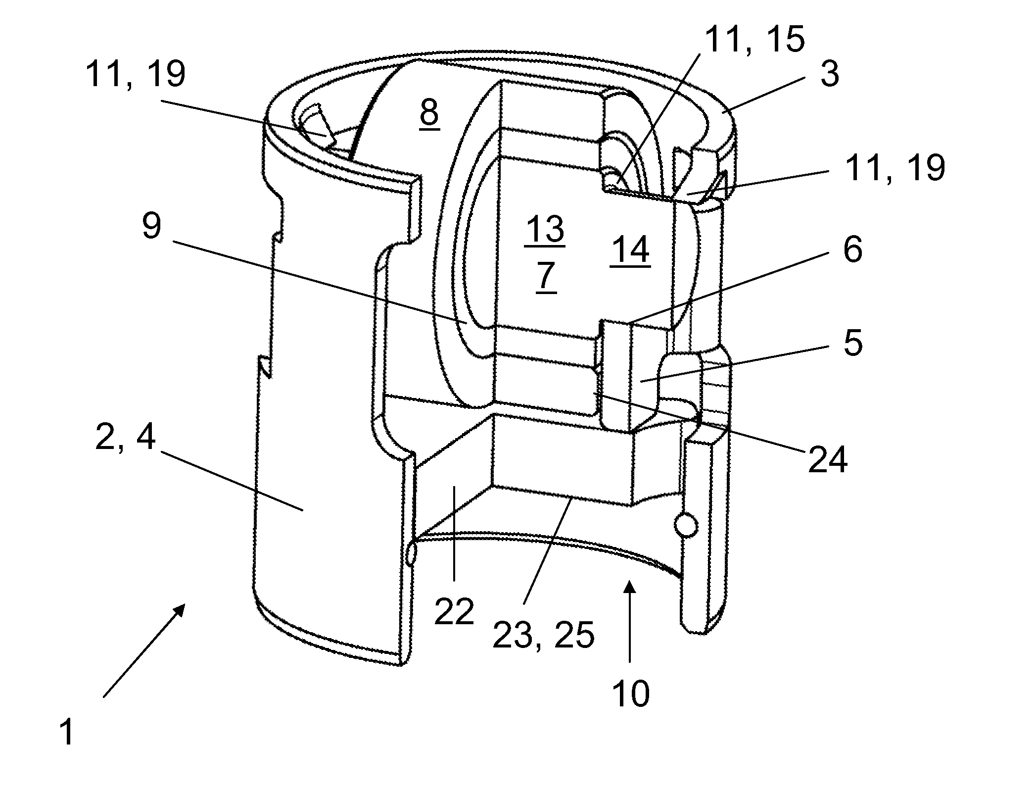
[0018]FIG. 1 discloses a roller tappet 1 comprising a housing 2 made out of thin-walled sheet steel, in the present case, for a high pressure fuel pump. In the vicinity of a drive side front end 3 of the roller tappet 1 are situated two opposing flats 5 that recede integrally from an outer wall 4 of the housing 2 while comprising, each one, a reception 6 having a U-like shape that is open in the direction of the drive side front end 3. A pin 7 is mounted in the receptions 6. A roller 8 serving as a run-on surface of a cam or an eccentric being mounted through a bearing means 9 on said pin 7. The bearing means is a needle roller bearing or a sliding bearing or a combination of these.

[0019]A support 25 for a pump piston extends near a driven side front end 10 of the roller tappet 1 axially below the roller 8. This support 25 is situated on an underside 23 of a separate bridge member 22 that extends through the housing 2.

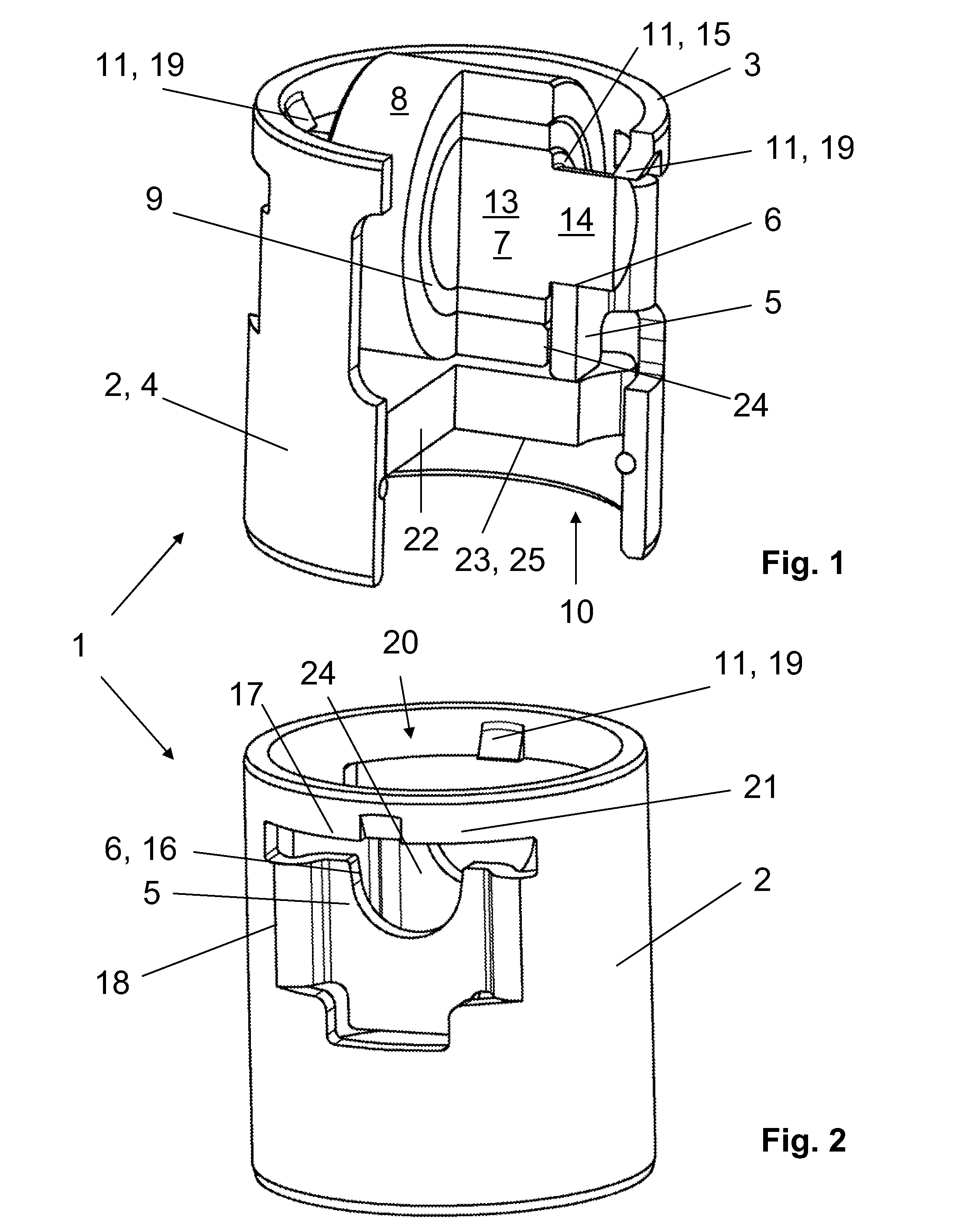
[0020]The invention further provides retention means 11 of a simp...


PUM


Abstract

A roller tappet intended for use a) in a high pressure fuel pump; b) in a valve train of an internal combustion engine; c) in an engine such as an axial piston engine or a radial piston engine; or d) generally for a pump/compressor of an axial piston type or of a radial piston type.

Description

CROSS-REFERENCE TO RELATED APPLICATIONS[0001]This application claims priority from German Patent Application No. 10 2012 202568.5 filed Feb. 20, 2012, which application is incorporated herein by reference in its entirety.FIELD OF THE INVENTION[0002]The invention concerns a roller tappet having a housing. Near a drive side front end of the housing, two diametrically opposing flats receding from an outer wall of the housing are arranged, each of the two flats comprising a reception with a U-like shape open in a direction towards the drive side front end, a pin being mounted in the receptions, a roller serving as a run-on surface of a periodic stroke producer being mounted through a bearing means on the pin, a support for a tappet follower element being seated on a driven side end of the housing, and a retention means being provided for the pin in an axial direction of the pin for preventing the pin from exiting axially out of the housing.BACKGROUND OF THE INVENTION[0003]A roller tappe...

Claims


Application Information

Patent Timeline
IPC IPC(8): F16H53/06
CPCF02M59/102F04B1/0408Y10T74/2107F16H53/06F04B1/0426F01L1/14
Inventor DORN, STEFANGEYER, NORBERT
Owner SCHAEFFLER TECH AG & CO KG
Why Eureka
Try Eureka