
Lithium ion secondary battery

Inactive Publication Date: 2013-08-22
NTT FACILITIES INC +1
View PDF5 Cites 8 Cited by
  • Summary
  • Abstract
  • Description
  • Claims
  • Application Information

AI Technical Summary

Benefits of technology

The present invention relates to a new battery design that reduces the risk of fire caused by battery abnormalities. This is accomplished by mixing flame retardant into the positive electrode mixture. Additionally, the pore size at the positive electrode mixture is set within a specific range to ensure the movement of lithium-ions and other important materials is not hindered during charging and discharging. As a result, the battery maintains its high rate discharge property.

Problems solved by technology

Further, it is being used for utilizing nature energy such as sunshine, wind force or the like as well as for leveling in use of electric power, and it is also being developed as a power source for industrial use such as an uninterruptible power supply apparatus or a construction machine.
In such a lithium-ion secondary battery, when it is exposed under a high temperature environment at a time of battery abnormality such as overcharge or the like, a battery constituting material such as a non-aqueous electrolyte or the like is likely to burn.
Further, oxygen generated by a thermal decomposition reaction of a positive electrode active material is likely to accelerate burning of the battery constituting material.

Method used


Image

  • Lithium ion secondary battery
  • Lithium ion secondary battery
  • Lithium ion secondary battery

Examples


example 1

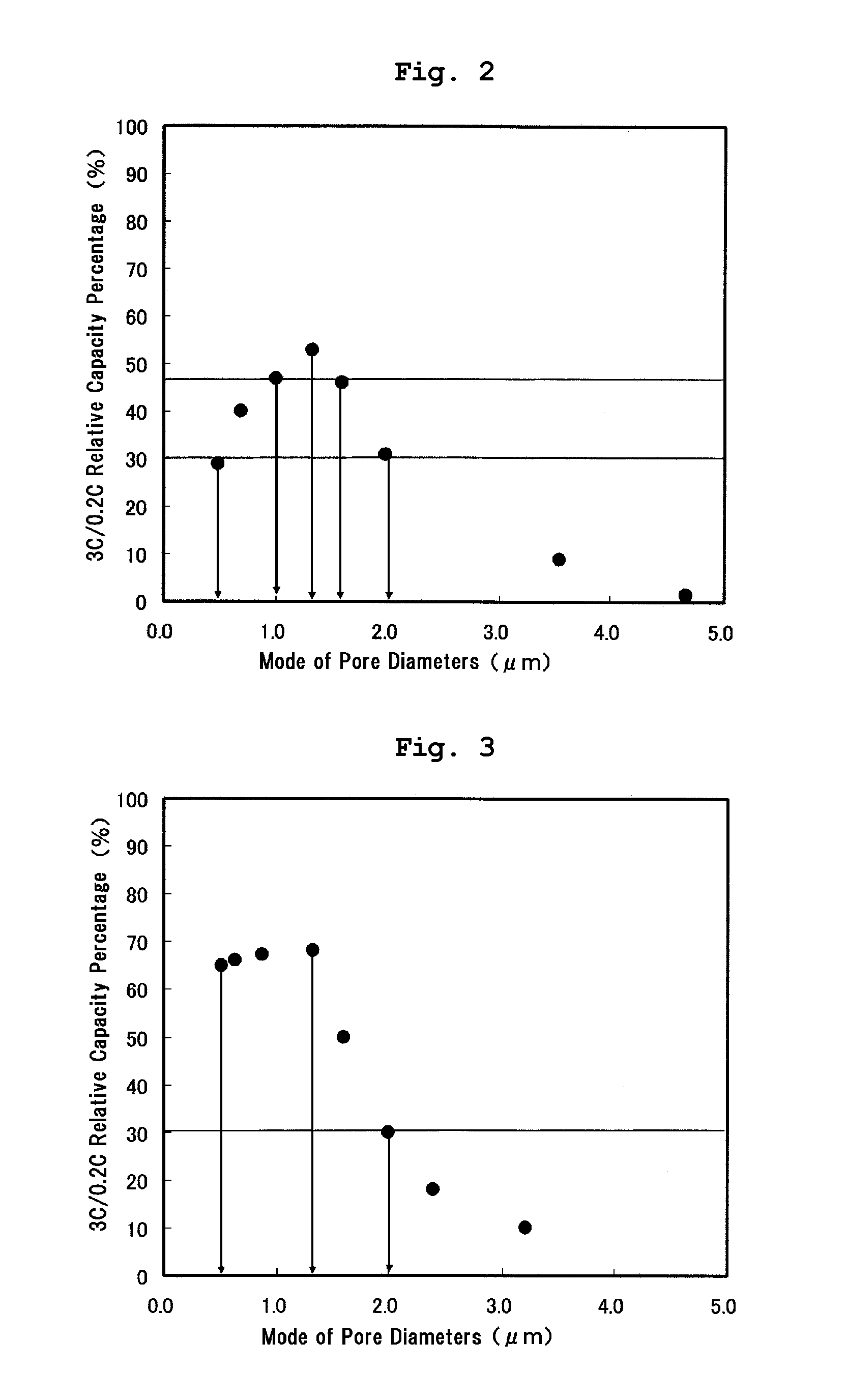
[0032]In Example 1, as shown in Table 1 below, the phosphazene compound (made by BRIDGESTONE CORP., Product Name: Phoslight (Registered Trademark), liquid state) of a flame retardant was mixed at 15 volume % into the non-aqueous electrolyte of which lithium salt density is 1.0M. The positive electrode mixture was formed by mixing 4 wt % of the phosphazene compound (made by BRIDGESTONE CORP., Product Name: Phoslight (Registered Trademark), solid state) of a flame retardant, 84 wt % of lithium manganate powder of a positive electrode active material, 5 wt % of scale graphite and 7 wt % of PVDF. A mode of pore diameters formed at the positive electrode mixture was measured by using a mercury porosimetry (SHIMADZU CORPORATION, Autopore IV 9520) to manufacture the lithium-ion secondary battery 1 in which the mode of pore diameters formed at the positive electrode mixture was set to 0.5 μm. In the same process, a plurality of lithium-ion secondary batteries of which mode of pore diameters...

example 2

[0033]As shown in Table 1, in Example 2, a plurality of lithium-ion secondary batteries of which mode of pore diameters formed at the positive electrode mixture is different were manufactured in the same manner as Example 1 except that the non-aqueous electrolyte of which lithium salt density is 1.5M was used. The modes of pore diameters at the positive electrode mixture in these lithium-ion secondary batteries were 0.5 μm, 0.6 μm, 0.9 μm, 1.3 μm, 1.6 μm, 2.0 μm, 2.3 μm and 3.2 μm, respectively.

example 3

[0034]As shown in Table 1, in Example 3, a plurality of lithium-ion secondary batteries of which mode of pore diameters formed at the positive electrode mixture is different were manufactured in the same manner as Example 1 except that the non-aqueous electrolyte of which lithium salt density is 1.5M was used and 2 wt % of the phosphazene compound was mixed to the positive electrode mixture. The modes of pore diameters at the positive electrode mixture in these lithium-ion secondary batteries were 0.5 μm, 1.0 μm, 1.3 μm, 1.9 μm, 2.0 μm, 2.2 μm, 2.8 μm and 3.0 μm, respectively.


PUM


Abstract

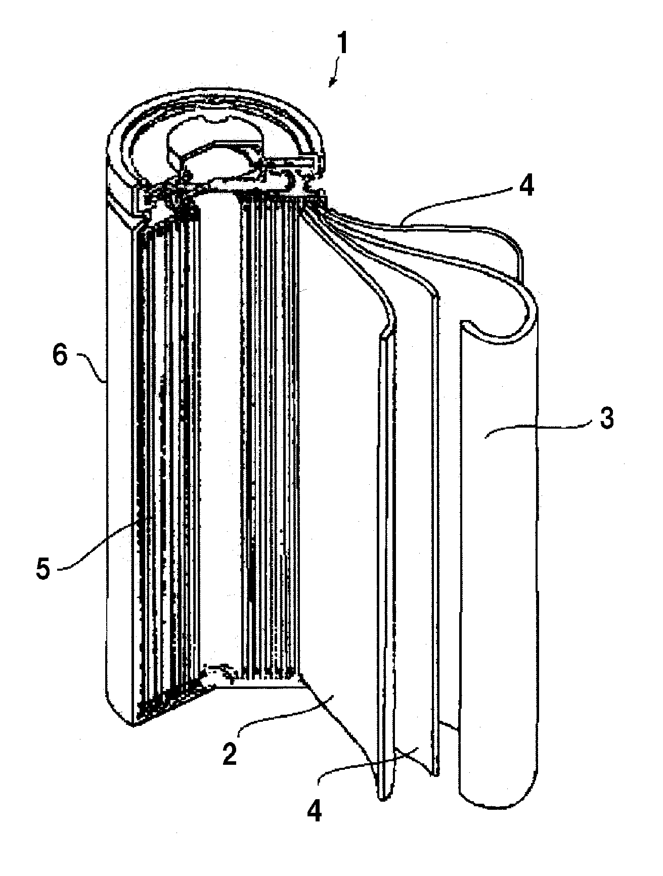
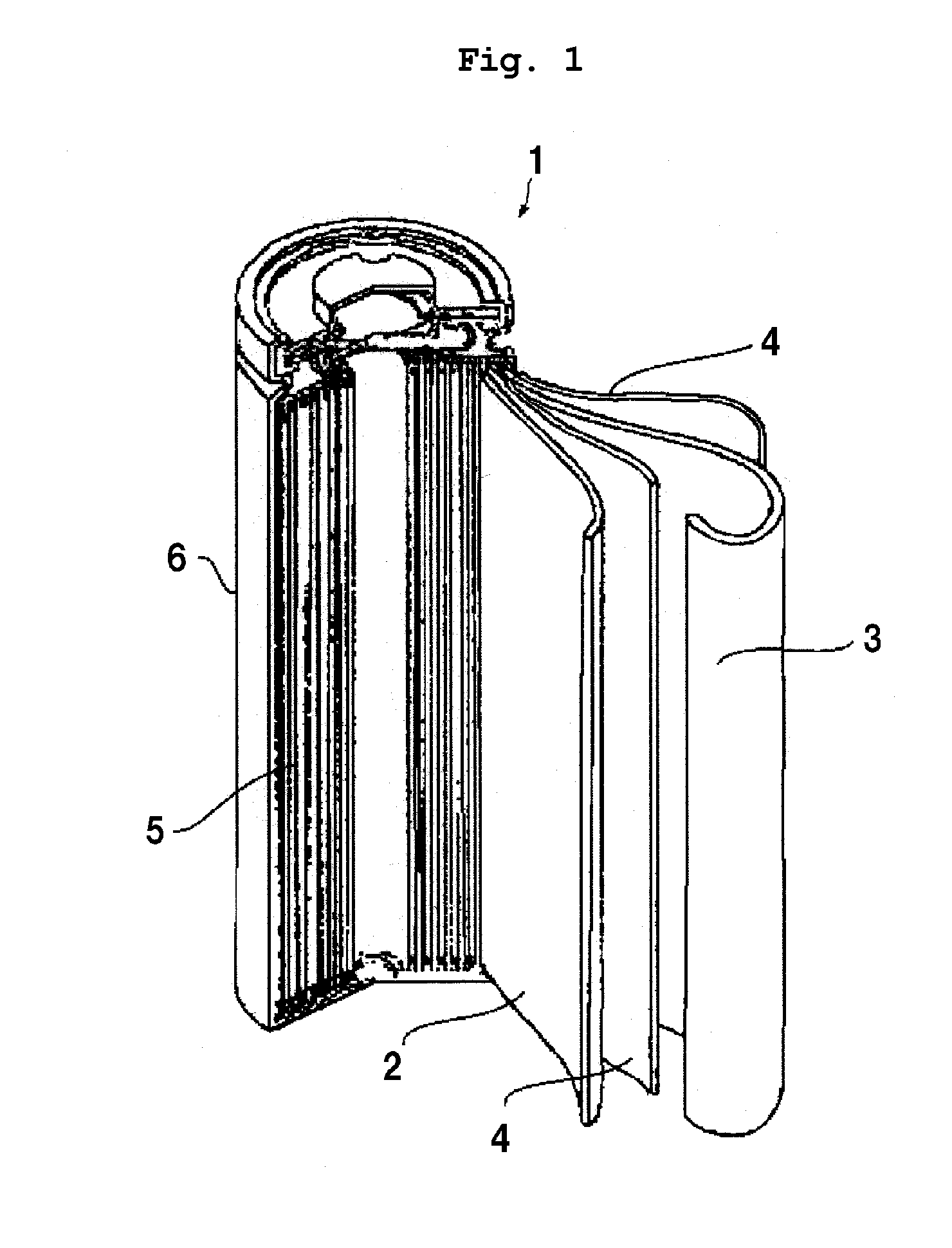
A lithium-ion secondary battery capable of securing safety at a time of battery abnormality and restricting a drop in a high rate discharge property is provided. A lithium-ion secondary battery 1 has an electrode group 5 formed by winding a positive electrode plate 2 in which a positive electrode mixture including a positive electrode active material is formed at a collector and a negative electrode plate 3 in which a negative electrode mixture including a negative electrode active material is formed at a collector via a porous separator 4. A flame retardant is mixed to the positive electrode mixture of the positive electrode plate 2. The mode of pore diameters formed at the positive electrode mixture, which is measured by a mercury porosimetry, is set to a range of from 0.5 to 2.0 μm. The moving path for lithium-ions and at the same time the moving path for electrons are secured at a charge / discharge time.

Description

FIELD OF THE INVENTION[0001]The present invention relates to a lithium-ion secondary battery, and more particularly to a lithium-ion secondary battery that an electrode group which a positive electrode having a positive electrode mixture containing a positive electrode active material and a negative electrode having a negative electrode mixture containing a negative electrode active material are disposed via a separator is infiltrated by a non-aqueous electrolyte which a lithium salt is mixed into an organic solvent to be accommodated into a battery container.DESCRIPTION OF RELATED ART[0002]A lithium-ion secondary battery enables miniaturization and lightening of a power source because of its high energy density. For this reason, it is being used not only as a small power source for mobile use but as a power source for electric vehicles . Further, it is being used for utilizing nature energy such as sunshine, wind force or the like as well as for leveling in use of electric power, a...

Claims


Application Information

Patent Timeline
IPC IPC(8): H01M10/42
CPCH01M4/62H01M10/0525H01M10/4235Y02T10/7011H01M4/628Y02E60/122H01M4/131H01M4/505H01M2004/021Y02E60/10H01M10/0568
Inventor TSUJIKAWA, TOMONOBUARAKAWA, MASAYASUMIYAMOTO, YOSHIKIHAYASHI, KOJINAKAHARA, MASAKI
Owner NTT FACILITIES INC
Learn More