Flywheel Mechanical Energy Derived from Engine Exhaust Heat

a technology of mechanical energy and engine exhaust, which is applied in the field of flywheel and clutch subsyste, can solve the problems of long-standing loss of engine heat energy from internal combustion engines, and none of such systems have employed the capability of transient storage and use of purely mechanical energy

Active Publication Date: 2013-08-29
CATERPILLAR INC
View PDF8 Cites 19 Cited by
  • Summary
  • Abstract
  • Description
  • Claims
  • Application Information

AI Technical Summary

Problems solved by technology

Loss of engine heat energy from internal combustion engines has long been an issue for designers of engines and engine exhaust systems.
Although most of the above described energy recovery systems have been successful in capturing and converting thermal energy into electrical power, for example for restoring energy into batteries, none of such systems have employed capabilities for the transient storage and use of purely mechanical energy.

Method used


Image

  • Flywheel Mechanical Energy Derived from Engine Exhaust Heat
  • Flywheel Mechanical Energy Derived from Engine Exhaust Heat
  • Flywheel Mechanical Energy Derived from Engine Exhaust Heat

Examples


Embodiment Construction

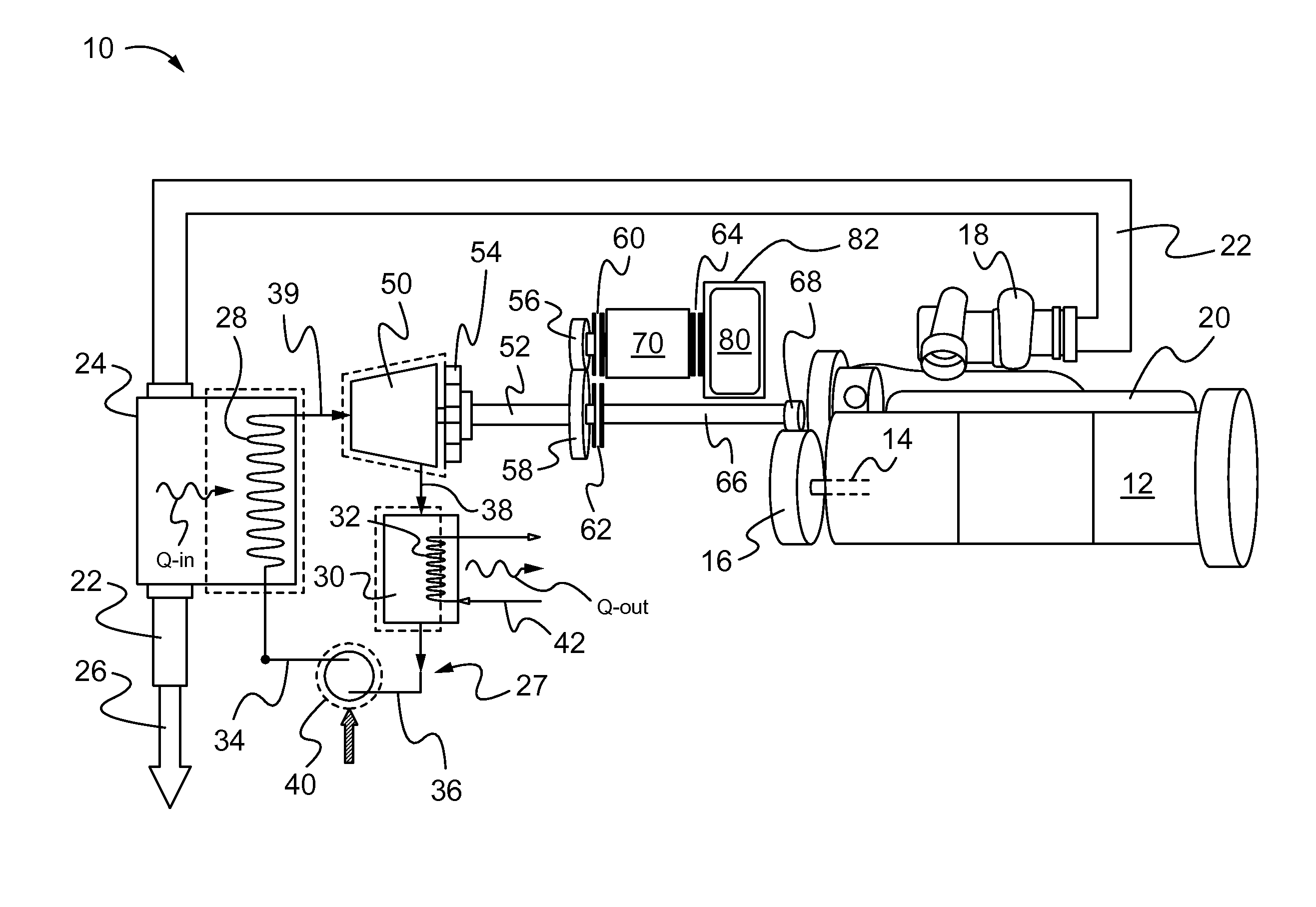
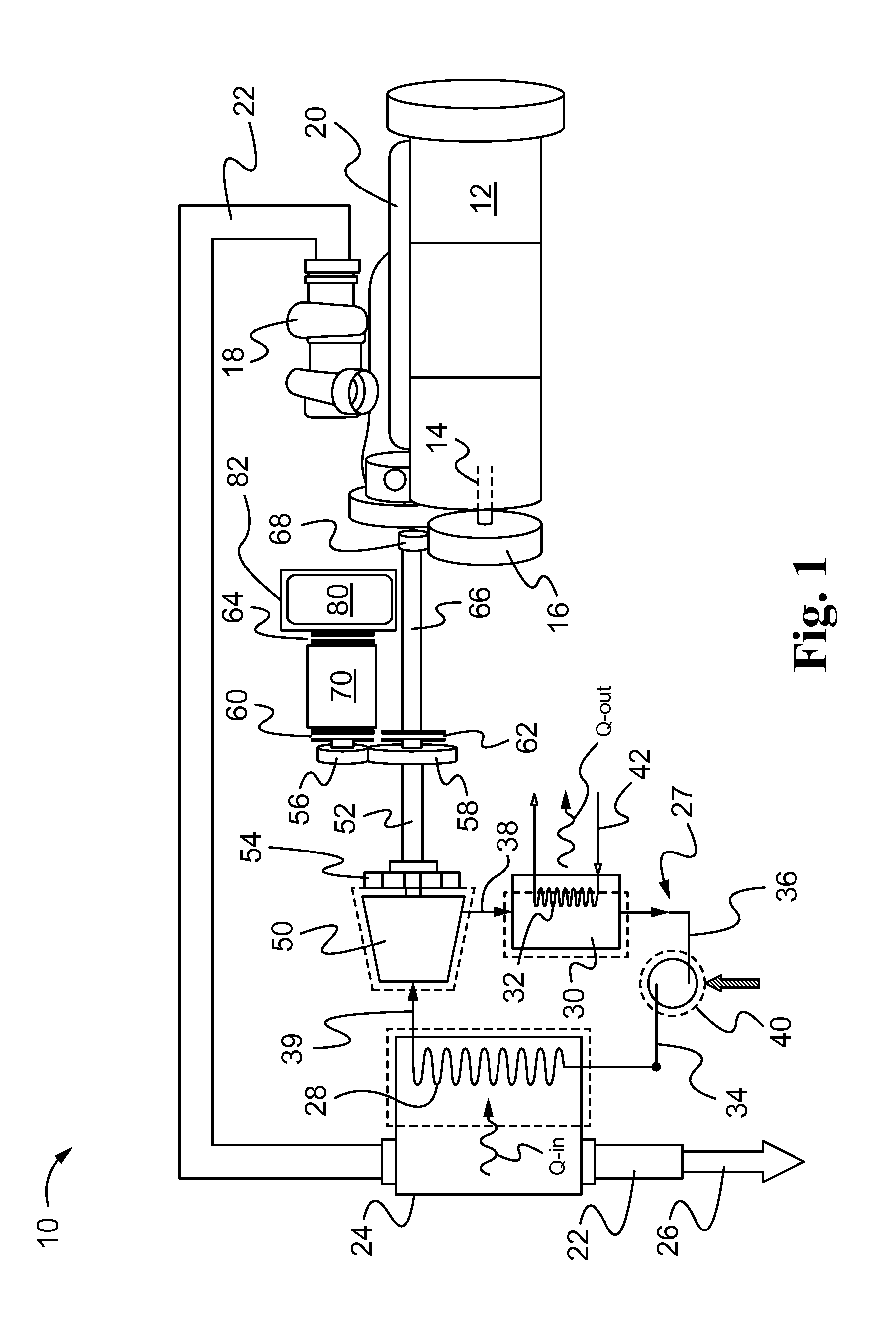
[0012]Referring initially to FIG. 1, an engine exhaust heat recovery system 10 is displayed in accordance with one disclosed embodiment. The heat recovery system 10 includes an engine 12, having an engine crankshaft 14, shown in phantom. The crankshaft 14 rotates an engine output gear 16, as shown.

[0013]A turbocharger 18 is situated atop of an exhaust gas header 20 of the engine 12. An exhaust gas conduit 22 extends from one end of the turbocharger 18 as shown. The exhaust gas conduit 22 discharges into a first heat exchanger, a boiler 24 in the embodiment shown, and heat shown as Q-in, is transferred from engine exhaust gases 26 passing through the conduit 22.

[0014]Those skilled in the art will appreciate that a single closed loop fluid 27 may be employed to accommodate transfer of energy from the hot exhaust gases 26. For this purpose, boiler coils 28 may enable the passage of the fluid 27 through the closed loop fluid system described herein. Ideally, the fluid 27 is two-phased, ...


PUM


Abstract

An engine exhaust heat recovery system includes an engine exhaust heat conduit that interacts with a two-phase fluid that exists in liquid and gaseous states within a single closed loop. A first heat exchanger, which may be a boiler, interfaces with and receives heat from the engine exhaust conduit. Exhaust heat energy converts the fluid from the liquid state into the gaseous state for transfer into a heat expander situated downstream of the first heat exchanger. The heat expander utilizes the gaseous heat energy to rotate a flywheel, and a system of clutches is situated and adapted to permit the flywheel to transfer mechanical energy for subsequent, selective production of work upon demand. In one disclosed embodiment, the heat expander may be a high-speed turbine with a rotary power shaft coupled to a transmission and a plurality of clutches adapted to engage and actuate the flywheel.

Description

TECHNICAL FIELD[0001]This disclosure relates to the capture and use of heat energy derived from internal combustion engine exhaust gases using a closed loop fluid heat transfer system. More particularly, the disclosure relates to a flywheel and clutch subsystem that may be powered by such a heat recovery mechanism to meet transient mechanical energy demands.BACKGROUND[0002]Loss of engine heat energy from internal combustion engines has long been an issue for designers of engines and engine exhaust systems. Numerous efforts have been made to reduce and / or capture at least a portion of such energy losses, in many cases with varying degrees of success.[0003]Some energy recovery systems have utilized Rankine cycles, employing fluids adapted to accommodate thermal energy transfers between boiler and condenser units. Other energy recovery systems have utilized dual fluids in more complex systems, typically involving parallel closed systems for accommodating transfers of heat energy betwee...

Claims


Application Information

Patent Timeline
Patent Type & Authority Applications(United States)
IPC IPC(8): F02B37/00F02B75/00
CPCY02T10/16F01N5/02F01K23/065F02G5/02F01K15/02F01K23/06F02B37/00Y02T10/12F01K5/02
Inventor JENSEN, JEFFREY EDWARD
Owner CATERPILLAR INC
Why Eureka
Try Eureka