Carbon dioxide absorbent fluid for a carbon dioxide sequestering system on a vehicle

a technology of carbon dioxide sequestering system and carbon dioxide absorbent fluid, which is applied in the direction of separation process, machine/engine, mechanical apparatus, etc., can solve the problem of reducing the operating efficiency of the vehicle on which they are installed

Active Publication Date: 2013-08-29
DELPHI TECH IP LTD
View PDF5 Cites 29 Cited by
  • Summary
  • Abstract
  • Description
  • Claims
  • Application Information

AI Technical Summary

Problems solved by technology

However, such systems often reduce operating e...

Method used


Image

  • Carbon dioxide absorbent fluid for a carbon dioxide sequestering system on a vehicle
  • Carbon dioxide absorbent fluid for a carbon dioxide sequestering system on a vehicle
  • Carbon dioxide absorbent fluid for a carbon dioxide sequestering system on a vehicle

Examples


Embodiment Construction

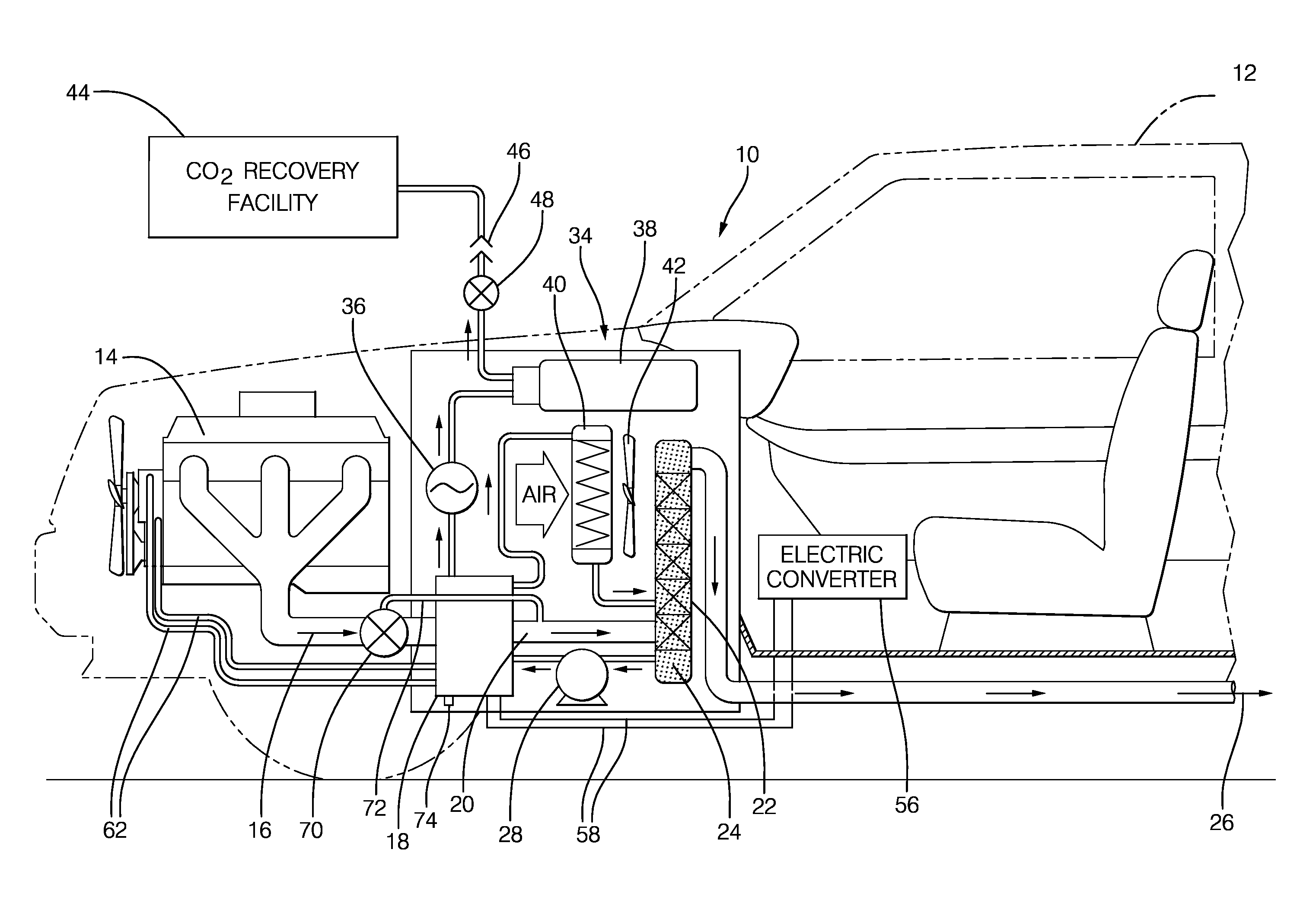
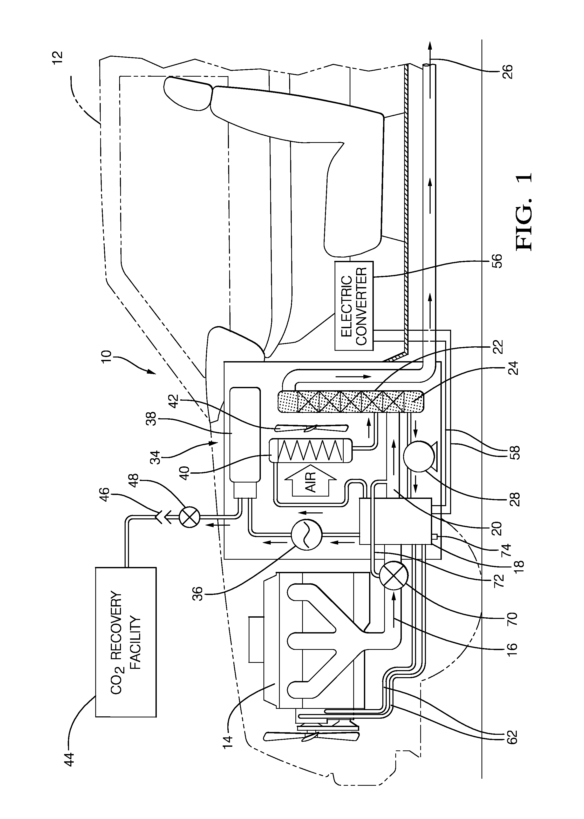
[0011]FIG. 1 illustrates a non-limiting example of vehicle 12 equipped with an embodiment of a system 10 for separating carbon dioxide gas from exhaust gas 16 emitted by internal combustion engine 14. In this example, the internal combustion engine 14 that may be configured to propel the vehicle 12. However, stationary applications of engines are contemplated. Examples of suitable internal combustion engines include, but are not limited to, gasoline spark-ignition engines, compression ignition engines fueled with gasoline or diesel fuel, turbine engines, hybrid combustion / electric engines, and fuel cells such as solid oxide fuel cells. In general, the internal combustion engine 14 emits exhaust gas 16 when operating, and the exhaust gas 16 is generally characterized as having an elevated temperature. The exhaust gas may also include elevated levels of carbon dioxide. While not specifically shown, the exhaust gas will generally be downstream from known engine exhaust after treatment ...


PUM

PropertyMeasurementUnit
Molar massaaaaaaaaaa

Abstract

A carbon dioxide storage means stores the carbon dioxide released in a heat exchanger. The heat exchanger cools the exhaust gas emitted by the internal combustion engine, and includes a thermal electric generator (TEG) configured to couple thermally the exhaust gas chamber to the absorber fluid chamber in a manner effective to heat the CO2 absorbent fluid by heat from the engine exhaust to release CO2 gas from the CO2 absorbent fluid and generate electricity in response to a temperature difference therebetween. The CO2 absorbent fluid is one of: a) an aliphatic di-functional nitrile (e.g. pimelonitrile); and b) an oligomeric poly-acrylonitrile (PAN).

Description

CROSS-REFERENCE TO RELATED APPLICATION[0001]This application is a continuation-in-part application and claims the benefit under 35 U.S.C.§120 of U.S. patent application Ser. No. 12 / 980,528, filed Dec. 29, 2010, the entire disclosure of which is hereby incorporated herein by reference.TECHNICAL FIELD OF INVENTION[0002]The invention generally relates to a system using a carbon dioxide absorbent fluid for separating or capturing carbon dioxide gas from internal combustion engine exhaust and then storing that gas. More particularly, the invention relates to the chemical used as the carbon dioxide absorbent fluid in the system.BACKGROUND OF INVENTION[0003]There is a continuing effort to increase the operating efficiency of vehicles, and reduce emissions. Internal combustion engine in vehicles generally emit carbon dioxide (CO2) as a by-product of an internal combustion process. Systems that extract CO2 from engine exhaust have been proposed. However, such systems often reduce operating e...

Claims


Application Information

Patent Timeline
IPC IPC(8): B01D53/14
CPCF01N5/025Y02C10/06Y02T10/20F01N3/04F01N3/0857B01D2257/504F01N2240/02F01N2570/10B01D53/1475Y02T10/16B01D53/92F01N3/0871Y02C20/40Y02T10/12
Inventor IHMS, DAVID W.MYERS, BRUCE A.
Owner DELPHI TECH IP LTD
Why Eureka
Try Eureka