Fundus camera with strip-shaped pupil division, and method for recording artifact-free, high-resolution fundus images

a fundus camera and strip-shaped technology, applied in the field offundus cameras, can solve the problems of not being able to suppress interference signals, not being able to achieve good suppression of interference signals, not being able to achieve cslos, etc., and achieves low manufacturing costs and simple design.

Active Publication Date: 2013-08-29
CARL ZEISS MEDITEC AG
View PDF3 Cites 31 Cited by
  • Summary
  • Abstract
  • Description
  • Claims
  • Application Information

AI Technical Summary

Benefits of technology

[0012]The present invention includes a specialized type of illumination for a fundus camera, by application of which it is possible to record high-resolution color fundus images without visible artifacts. The fundus camera is able to image a fundus angle of 45° in the absence of mydriatic drops and for non-dark-adapted eyes, i.e., for a pupil diameter of approximately 2 mm. To reliably exclude possible contact with the eye during adjustment of the fundus camera, the fundus camera or its boundary facing the eye is situated at a distance less than approximately 10-20 mm from the eye. Despite low manufacturing costs, a simple design, and problem-free adjustability to the eye to be examined, the fundus camera achieves resolutions of 60 Ip / mm in the center of the image field.
[0015]The present fundus camera, according to an embodiment of the invention, having a strip-shaped pupil division is provided for recording high-resolution color images of the fundus, wherein for this purpose the eyes are not dark-adapted, and no mydriatic drops have been used. In addition to the fundus cameras known from the prior art and described above, the proposed approach represents an alternative which may find widespread application due to its simple design and low manufacturing costs.

Problems solved by technology

Pupil diameters of 2 mm, which occur in non-dark-adapted eyes, are not possible.
However, the suppression of interference signals is generally not as good as in CSLOs.
For this reason, the CSLOs, which are generally quite expensive, are used primarily as “high end” devices which allow very high-quality fundus recordings, but which are much more difficult to adjust to the eye to be measured compared to, for example, the wide-field fundus cameras mentioned in the first group.
Another disadvantage of scanning laser ophthalmoscopes is that recording a color fundus image by the scanning process takes considerably longer than for wide-field systems.
The motion artifacts which result, in particular in restless patients, additionally complicate and / or impair the recordings.
Another limitation in the use of CSLOs is their high level of technical complexity and the resulting higher acquisition costs, for which reason they are seldom used in the “low end” sector.
Despite these major advantages, fundus cameras having transscleral illumination have not become established on the market since their development by Pomeratzeff (1974).
Significant application-related limitations result from this direct contact between the illumination optical fiber and the eye.
Each of these three groups of fundus imaging devices has specific advantages as well as disadvantages, but none is able to meet all required specifications.

Method used


Image

  • Fundus camera with strip-shaped pupil division, and method for recording artifact-free, high-resolution fundus images
  • Fundus camera with strip-shaped pupil division, and method for recording artifact-free, high-resolution fundus images
  • Fundus camera with strip-shaped pupil division, and method for recording artifact-free, high-resolution fundus images

Examples


Embodiment Construction

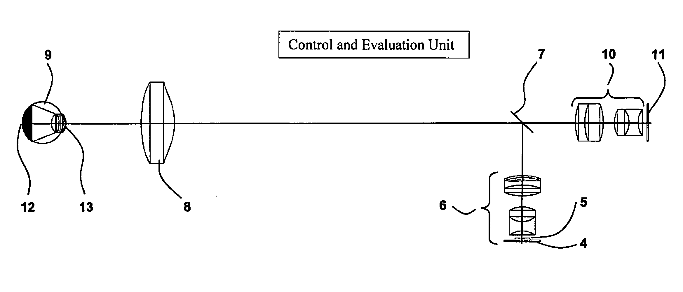
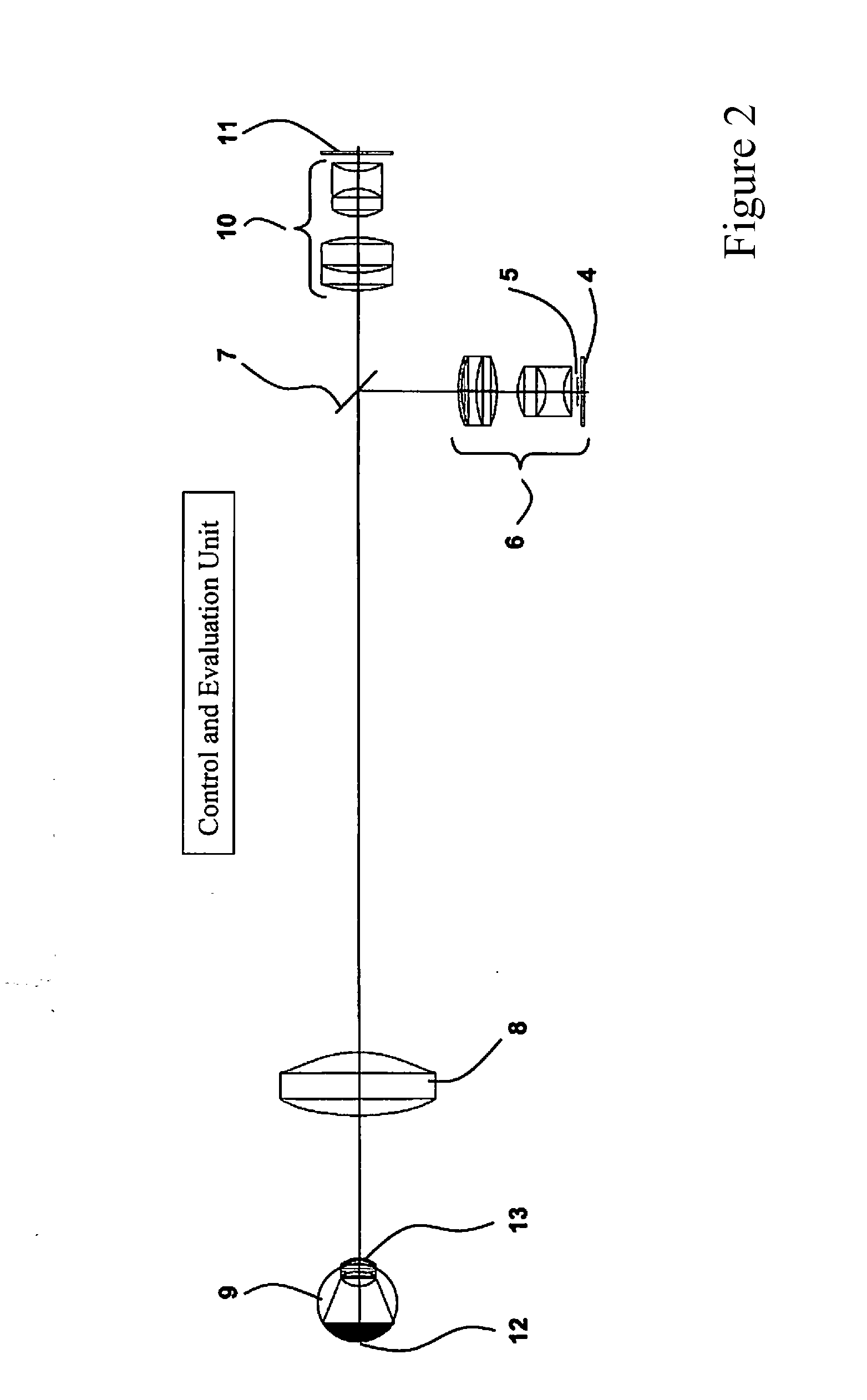
[0023]The fundus camera according to an embodiment of the invention having strip-shaped pupil division includes an illumination source having illumination optics, a deflecting mirror, and an ophthalmoscope lens for illuminating the eye, detection optics and a detector for imaging the light reflected from the eye, as well as a control and evaluation unit. In particular, a coherent or incoherent illumination source is present. Furthermore, the deflecting mirror has a strip shape, and the detector having a spatially resolving characteristic is activatable and readable sector by sector. For this purpose, the control and evaluation unit is able to link the data, read out sector by sector from the detector, in the form of a bright image to produce a resulting fundus image.

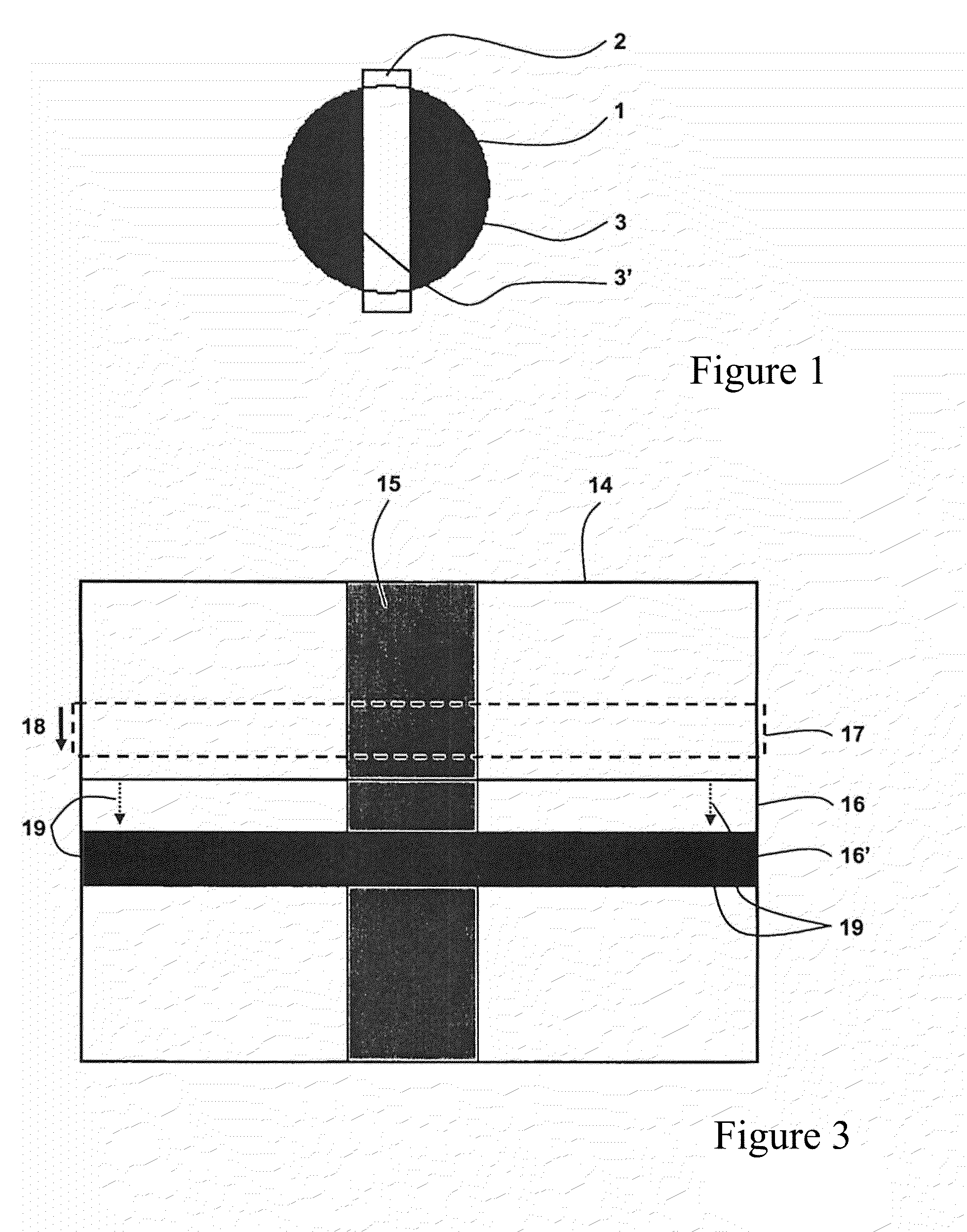
[0024]In this regard, FIG. 1 is a schematic diagram concerning strip-shaped pupil division of the eye to be examined. The light vertical bar denotes the illumination zone 2, while the two gray circular segments 3 and 3′ ...


PUM


Abstract

A fundus camera for the recording of high-resolution colour images of the fundus of non-dark-adapted eyes, and without the use of a mydriatic. The fundus camera has a strip-shaped pupil division, and includes a coherent or incoherent illumination source with illumination optics, a deflection mirror and an ophthalmoscope lens for illuminating the eye, detection optics and a detector for detecting the light reflected by the eye, and a control and evaluation unit. The deflection mirror has a strip shape, and the spatially resolving detector can be activated and read out in sectors. The control and evaluation unit connects the data read out in sectors in the form of a bright image from the detector and produce a resulting fundus image. The fundus camera records images of the fundus when the eyes are not dark-adapted for this purpose and no mydriatic has been used.

Description

RELATED APPLICATIONS[0001]The present application is a National Phase entry of PCT Application No. PCT / EP2011 / 005558, filed Nov. 4, 2011, which claims priority from DE Application No. 10 2010 050 693.1, filed Nov. 6, 2010, which applications are hereby incorporated by reference herein in their entirety.FIELD OF THE INVENTION[0002]The present invention relates to a fundus camera, having strip-shaped pupil division, for recording high-resolution color images of the fundus of non-dark-adapted eyes, and without the use of mydriatic drops.BACKGROUND[0003]The fundus cameras known from the prior art, by means of which artifacts of undesirable eye interfaces may be suppressed, may be divided into basically three optical device classes.[0004]Classical wide-field fundus cameras which use annular pupil division as the most important feature may be included in the first group. While the ocular fundus is illuminated by an external illumination ring, the light that is scattered back from the fund...

Claims


Application Information

Patent Timeline
Patent Type & Authority Applications(United States)
IPC IPC(8): A61B3/12
CPCA61B3/12A61B3/158A61B3/14
Inventor BUBLITZ, DANIELMULLER, LOTHARMOHRHOLZ, UWEMOHR, THOMASTEIGE, FRANK
Owner CARL ZEISS MEDITEC AG
Why Eureka
Try Eureka