
Decoupled Three-Phase Power Flow Analysis Method for Unbalanced Power Distribution Systems

a power flow analysis and three-phase technology, applied in the field of three-phase power flow analysis for unbalanced power distribution systems, can solve the problems of slow power flow analysis and inefficiency prevent its use for real-time applications, so as to reduce the computational burden of power flow analysis, improve accuracy, and reduce the admittance matrix

Active Publication Date: 2013-08-29
MITSUBISHI ELECTRIC RES LAB INC
View PDF10 Cites 34 Cited by
  • Summary
  • Abstract
  • Description
  • Claims
  • Application Information

AI Technical Summary

Benefits of technology

The patent describes a method for analyzing the power flow in distribution systems with a large number of nodes. The method is efficient and reduces the computational burden by factorizing the nodal admittance matrix into two smaller ones. The method also models the impact of zero-impedance branches and ensures that the three-phase active power remains constant and the voltage magnitudes balanced. Furthermore, the method accurately determines the required amount of reactive power compensation to correct voltage magnitude mismatches at PV nodes. The invention also suggests using a PV sensitivity matrix to determine the required reactive power compensation. Overall, the method improves accuracy, reduces computational load, and facilitates the analysis of power distribution systems.

Problems solved by technology

Considering the fact that rectangular coordinate equations are solved recursively, the size and a structure of the nodal admittance matrix make the power flow analysis slow.
In some situations, inefficiency of the power flow analysis prevents its usage for real time applications.

Method used


Image

  • Decoupled Three-Phase Power Flow Analysis Method for Unbalanced Power Distribution Systems
  • Decoupled Three-Phase Power Flow Analysis Method for Unbalanced Power Distribution Systems
  • Decoupled Three-Phase Power Flow Analysis Method for Unbalanced Power Distribution Systems

Examples


example

[0080]FIG. 6 shows a block diagram of a method 600 for analyzing a model of an unbalanced power distribution system according to one embodiment of the invention. Various embodiments of invention use at least part of the steps of the method 600.

[0081]In step 610, the slave bus of a zero-impedance branch is removed and the zero-impedance branch and its adjacent impedance branch are replaced with a new branch between the master bus of zero-impedance branch and one of adjacent branch buses as shown in FIG. 3. The nodal admittance of new branch is determined based on the nodal admittance matrix of adjacent branch and voltage and current amplifying factor matrices of zero-impedance branch. The load at the slave bus is modeled as an equivalent load at the master bus.

[0082]In step 615, the method determines the nodal admittance matrix of impedance branch connected with three phase PV buses with balanced voltages by replacing the three-phase PV bus with an equivalent single-phase PV bus mode...


PUM


Abstract

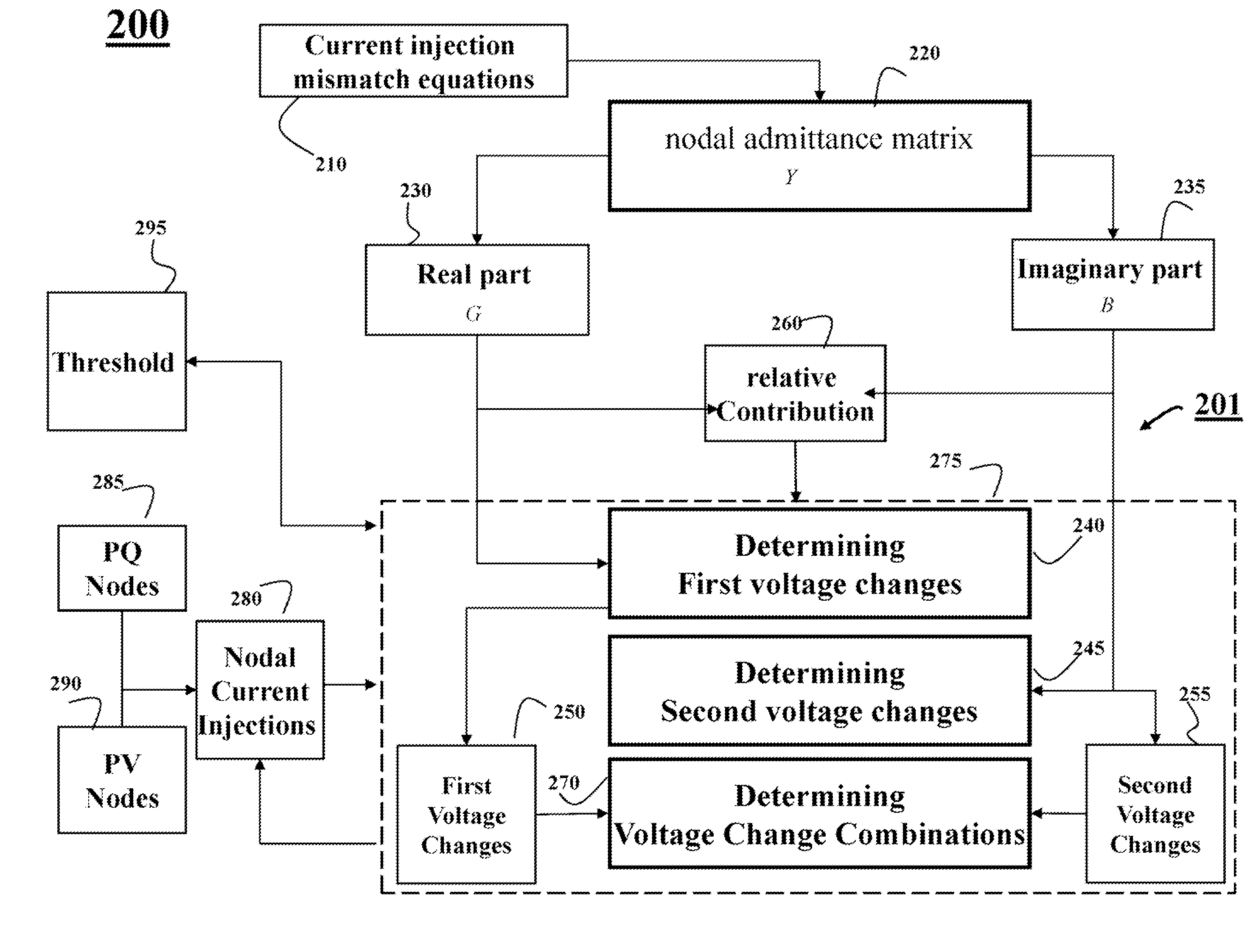
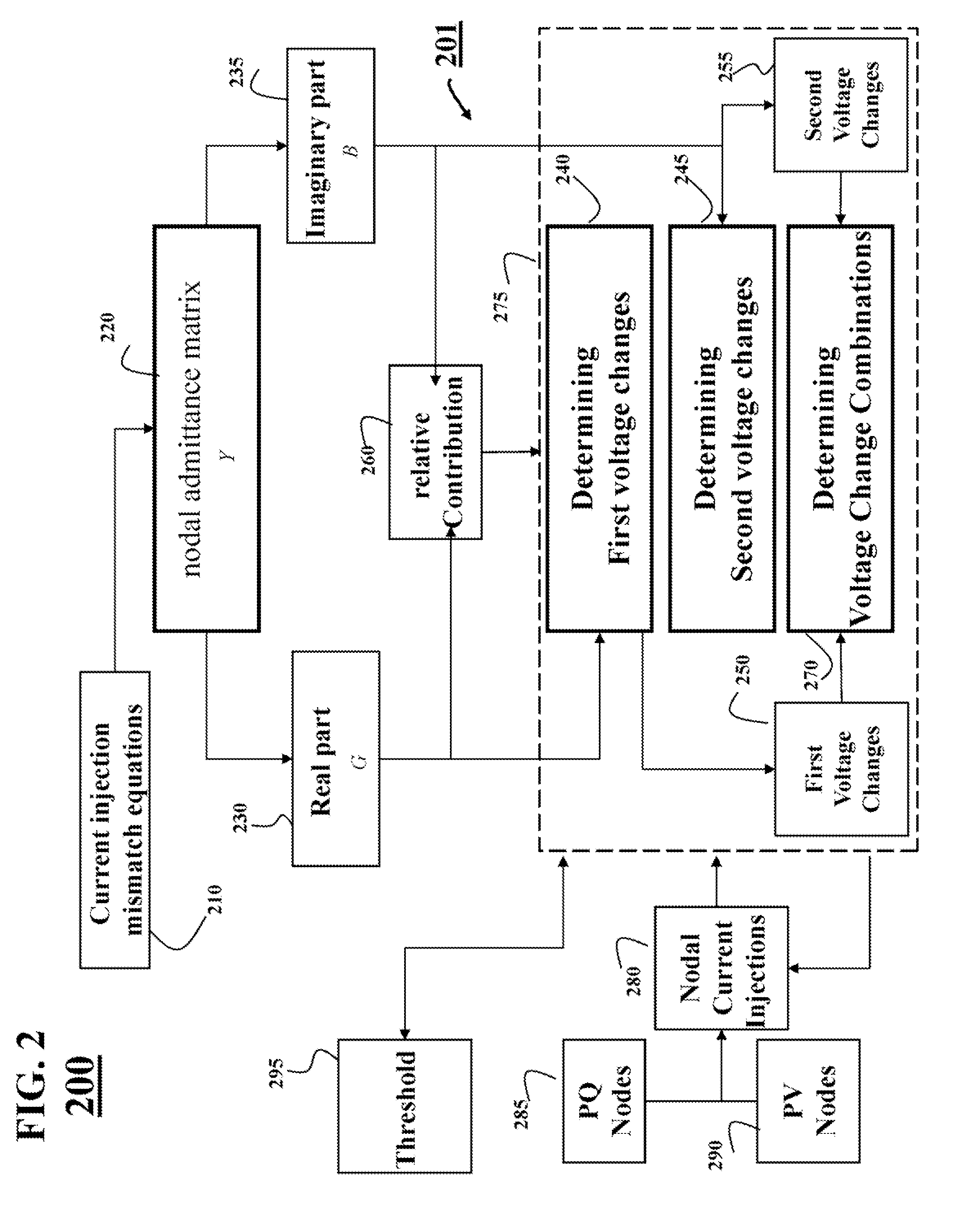
Three phase power flow analysis of an unbalanced power distribution system decouples voltage changes resulting from nodal admittance matrix into one contribution from a real part, conductance matrix, and other contribution from an imaginary part, and a susceptance matrix. A first voltage change and second voltage change resulting from conductance and susceptance matrices are determined respectively. The voltages of a node of the power distribution system are determined as a combination of first and second voltages.

Description

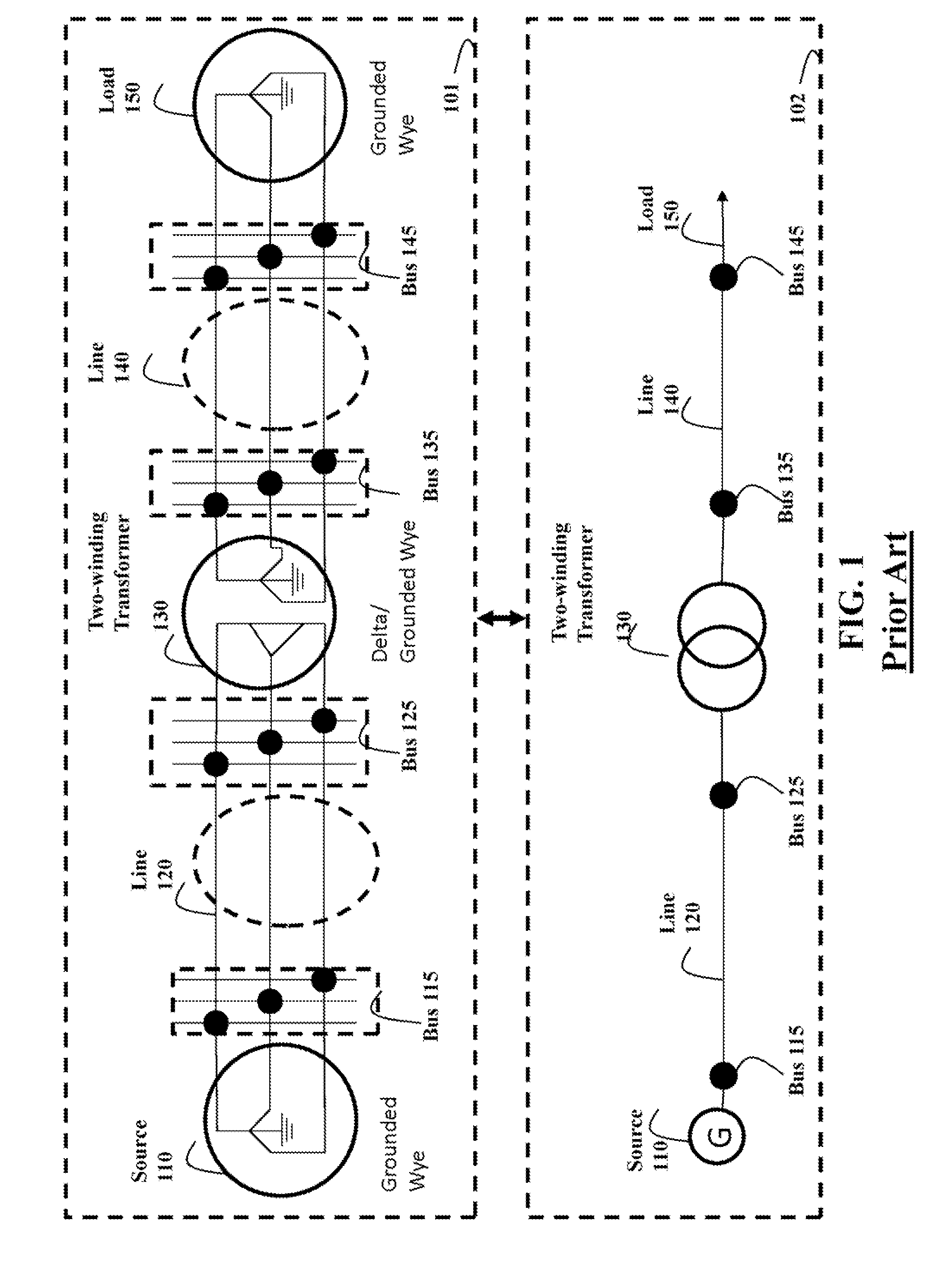
FIELD OF THE INVENTION[0001]This invention relates generally to power distribution systems, and more particularly to three-phase power flow analysis for unbalanced power distribution systems.BACKGROUND OF THE INVENTION[0002]Power distribution systems deliver electric powers from distributed generators and transmission systems to power consumers. The distribution system may be either a 3-phase 4 wire system, or a 3-phase 3 wire system. The power from the transmission system or the generators is delivered to the consumers through transmission lines, and various voltage regulation devices, such as shunt capacitors, step voltage regulators, and transformers. The consumer loads may be single phase, two-phase or three-phase. The loads may be constant power load, constant current load, or constant impedance load.[0003]FIG. 1 shows schematic diagrams of a sample distribution system including both the three-phase representation 101 and one-line diagram 102. The sample system includes one gro...

Claims


Application Information

Patent Timeline
IPC IPC(8): G06F19/00
CPCH02J3/26Y02E40/50
Inventor SUN, HONGBODUBEY, ANAMIKA
Owner MITSUBISHI ELECTRIC RES LAB INC
Learn More