Air introduction system and method for cooling towers

a technology of air introduction system and cooling tower, which is applied in the direction of trickle cooler, fuel gas production, liquid separation agent, etc., can solve the problems of large air quantity that flows upwards through the cooling tower in order to convey away the waste heat of the plant to be cooled, difficult to achieve the cooling efficiency achieved by direct cooling, and large air quantity

Inactive Publication Date: 2013-09-05
KERNKRAFTWERK LEIBSTADT +1
View PDF1 Cites 10 Cited by
  • Summary
  • Abstract
  • Description
  • Claims
  • Application Information

AI Technical Summary

Benefits of technology

[0031]According to a further variant of the invention, the said deflection surface is designed in such a way that objects falling down along the outer surface of the tower shell are able to be substantially led over smoothly to the deflection surface without discontinuity and be pushed outward by a deflection distance.

Problems solved by technology

However, the quantity of air that flows upwards through the cooling tower in order to convey away the waste heat of the plant to be cooled is also very large.
The conveying of the large air quantities is a challenging problem for the development of the towers.
Although the wet, dry and combined wet / dry operated cooling towers built so far fulfil by and large the striven-for energy-related goals, they are far from achieving the cooling efficiency that is achieved with direct cooling in which water from river, lake or the sea that flows directly through the power plant condensor is conducted back into the bodies of water directly.
Aside from the protection of valuable bodies of water, being called for in many places, the facilities equipped with air cooling are at a disadvantage owing to the higher investment costs, the size of these structures and the corresponding optical intrusion in the landscape.
These fills however have proven to be highly prone to soiling in many cases.
Through the soiling the fills basically lose their cooling efficiency, in many cases even very quickly, and reduce in this way the improvement that they are actually supposed to provide.
The annular flange of DE1501396 has the drawback that it has to be adapted precisely to the dimensions of a particular cooling tower, and has to be designed and built already during the construction of the cooling tower.
A further disadvantage of the annular flange of DE1501396 is that the desired air current is dependent on the formation of a “dead zone” of stagnant air below the flange.
The air supply in the cooling tower can also be greatly interfered with by rain in the rain zone.
Both systems have, however, big installations involving large amounts of time and effort and high costs.

Method used


Image

  • Air introduction system and method for cooling towers
  • Air introduction system and method for cooling towers
  • Air introduction system and method for cooling towers

Examples


Embodiment Construction

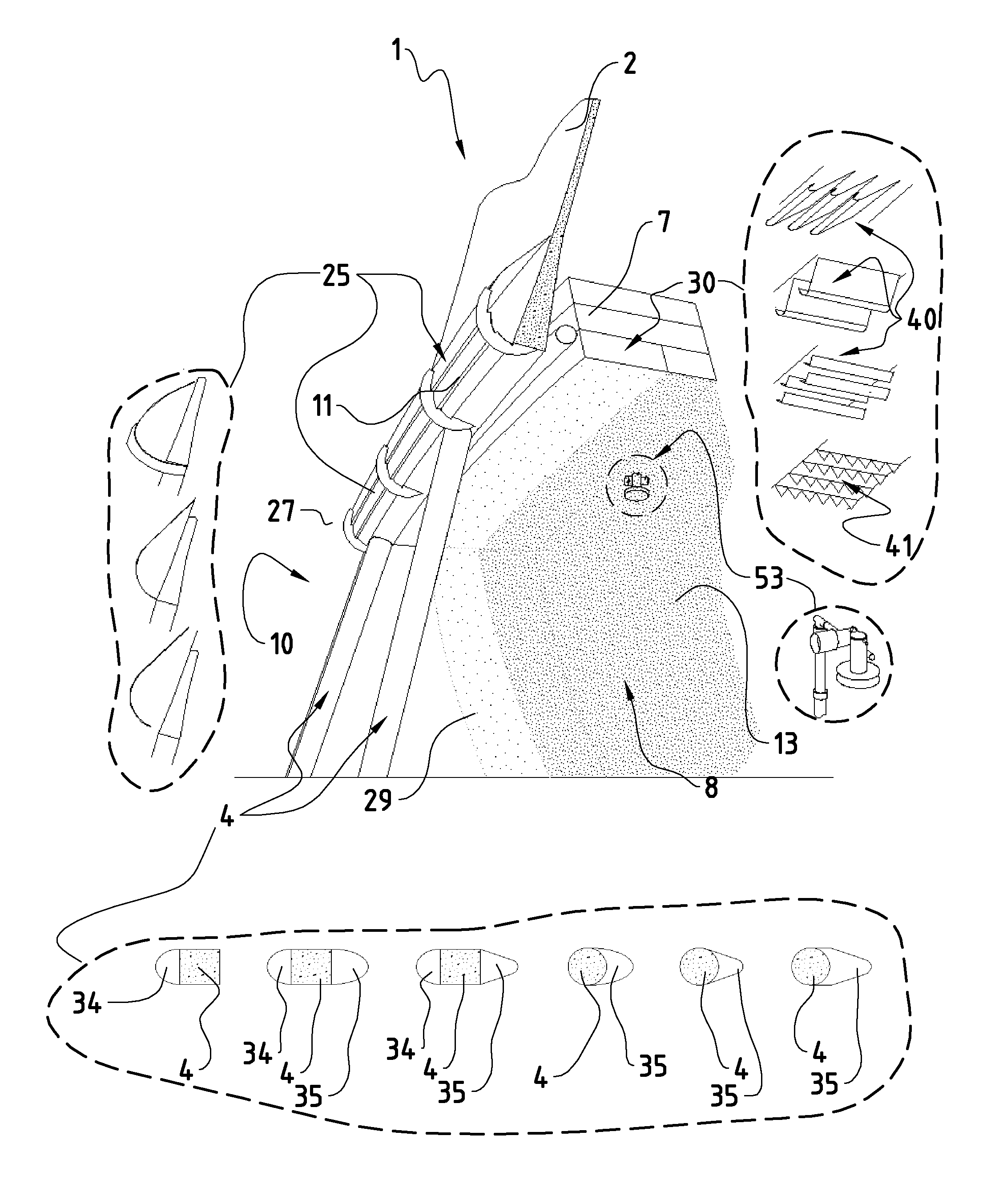
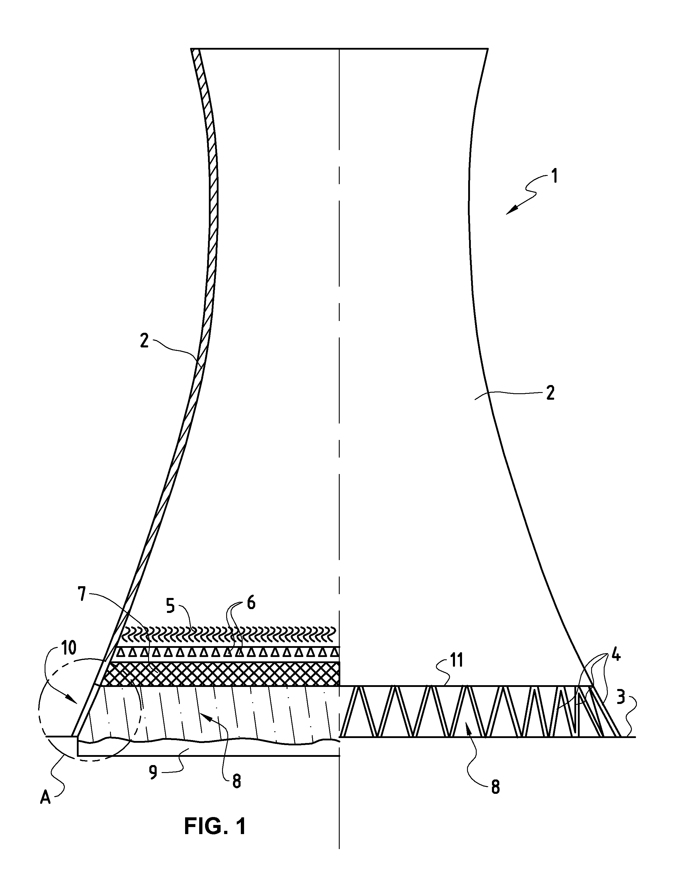
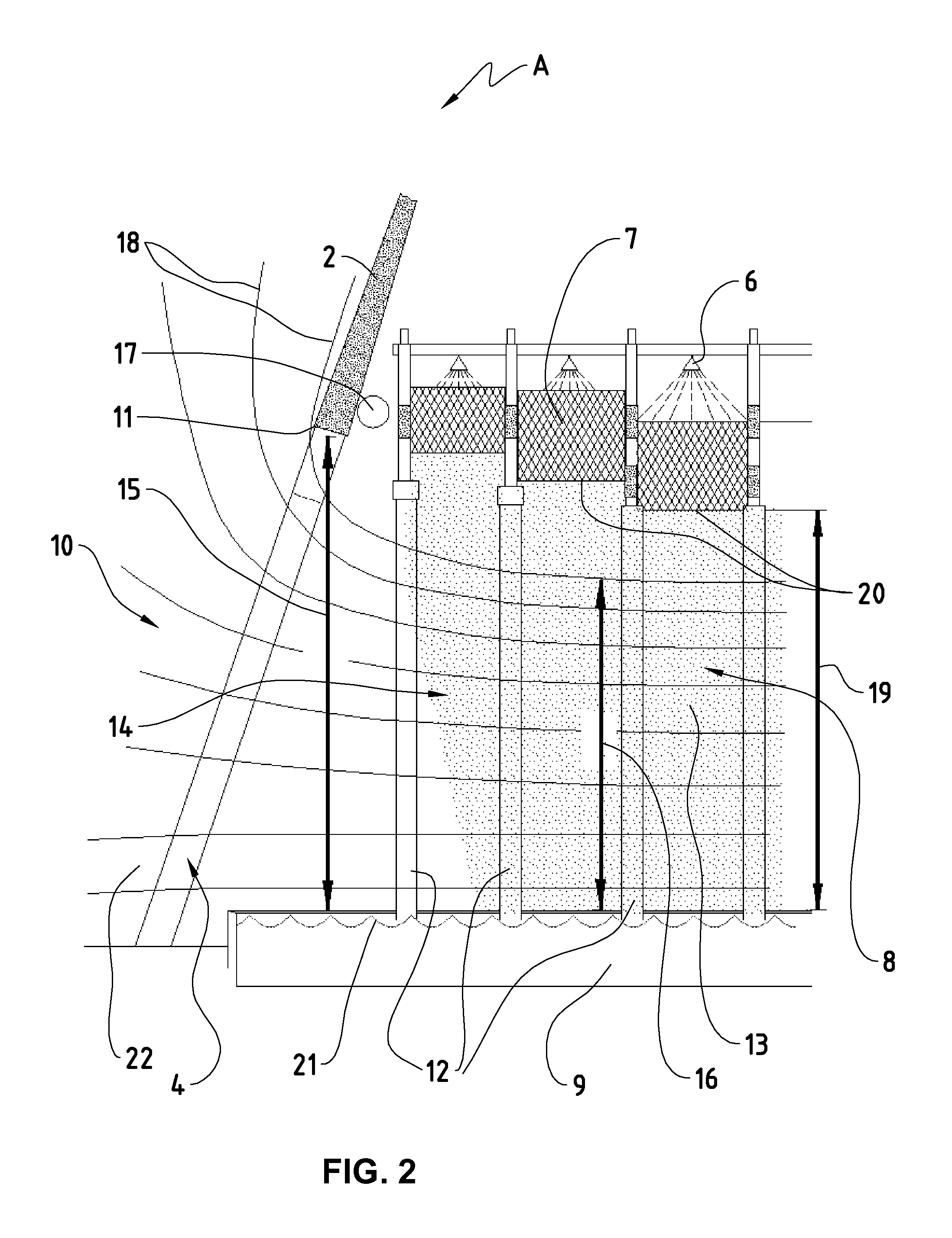
[0051]FIG. 1 shows as example a conventional wet cooling tower 1 with natural draft. Such a tower has a cooling tower shell 2 (also called shell or flue element), which is borne on the underlying support surface 3 by means of a set of supports 4. Air from the surrounding area of the tower is drawn in through the air inflow opening 10 (between the supports and between shell 2 and support surface 3). The air flows under through the air inflow opening 10 into the so-called rain zone 8 of the tower 1, where it is subsequently distributed. Coming out of the rain zone 8, the air rises up through the heat exchanger surfaces (the so-called fill 7), in counterflow to the downward flowing hot water from the condenser. The air then flows through the spray zone, in which the hot water is sprayed as evenly as possible on the fill 7 by thousands of firmly built-in spraying units 6. Droplet separators 5 finally free the rising air of small spray droplets, which arise through this spraying, before ...


PUM

PropertyMeasurementUnit
water vapor pressuresaaaaaaaaaa
air currentaaaaaaaaaa
heightaaaaaaaaaa

Abstract

A system and a method for promoting improved air flow through a cooling tower and reduced inner air pressure losses caused by rain in the rain zone of a cooling tower. Aerodynamic modules are mounted on the lower edge of the cooling tower shell in order to deflect the downward-flowing air about the lower edge of the tower shell and into the rain zone. The aerodynamic modules can be modularly mounted, can be replaced, and do not affect the statics of the tower shell. Aerodynamic modules can also be built on the base area to deflect the incoming air over any obstacles. Troughs or dripping elements can also promote flow by reducing the rain falling in an outer area.

Description

[0001]This invention relates to the discharge of waste heat from plants such as, for example, power plants and industrial plants. It relates in particular, but not exclusively however, to the conducting of cooling air through so-called wet or natural draft cooling towers.BACKGROUND ART[0002]To achieve a high degree of efficiency of work machines that are subject to the Clausius-Rankine cycle, such as e.g. steam turbines, it is necessary to carry out the steam / liquid phase transition of the working fluid in the power plant condenser at as low a condensation temperature as possible. At a temperature of 30° C., for example, water vapor pressures of about 40 mbar and less are reached.[0003]The waste heat inevitably arising in the work machines must be led away in the condenser to the surrounding area. The practical transfer of the waste heat in power plants or in large industrial plants, in which similar cooling requirements exist, but no direct cooling in the condenser by means of wate...

Claims


Application Information

Patent Timeline
Patent Type & Authority Applications(United States)
IPC IPC(8): F28F25/12B23P15/26
CPCE04H5/12F28C1/00F28F25/00Y10T29/49352B23P15/26F28F2250/02F28F25/12Y02B30/70
Inventor BOGH, PERYGRAF, PETERFISCH, KLEMENS
Owner KERNKRAFTWERK LEIBSTADT
Why Eureka
Try Eureka