X-ray imaging apparatus, control device, radiation imaging apparatus, and method of controlling the same
a radiation imaging and control device technology, applied in the field of xray imaging technique, can solve the problems of high reliability of the protocol, low transfer efficiency, and inability to meet the request to display in real time, and achieve the effect of reducing the delay in switching
- Summary
- Abstract
- Description
- Claims
- Application Information
AI Technical Summary
Benefits of technology
Problems solved by technology
Method used
Image
Examples
first embodiment
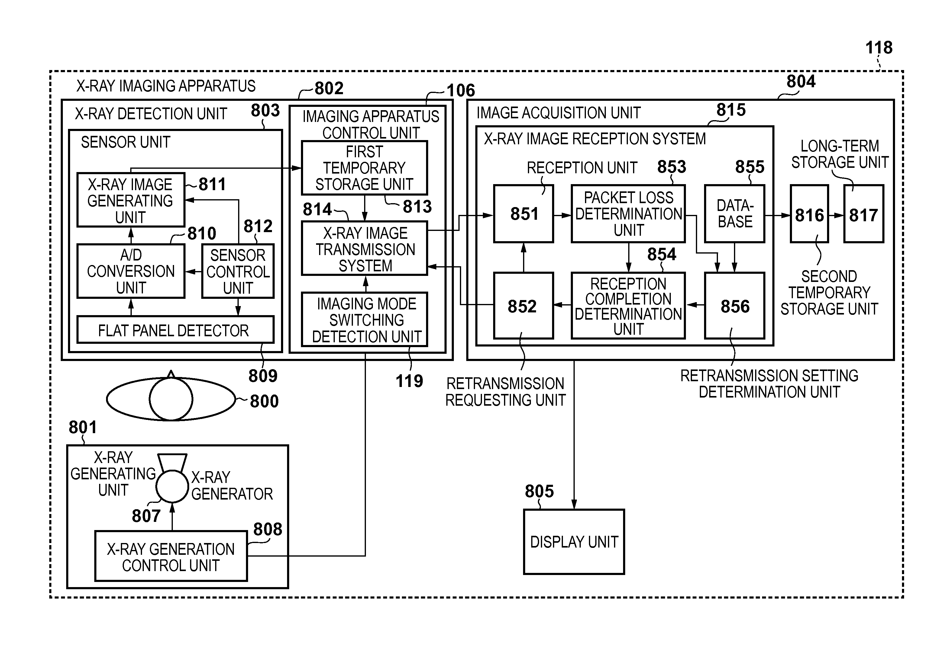
[0032]An example of the arrangement of an X-ray imaging apparatus which is an example of a radiation imaging apparatus according to this embodiment will be described first with reference to the block diagram of FIG. 8. An X-ray imaging apparatus 818 shown in FIG. 8 is roughly constituted by an X-ray generating unit 801, an X-ray detection unit 802, an image acquisition unit 804, and a display unit 805.
[0033]801>
[0034]The X-ray generating unit 801 will be described first. The X-ray generating unit 801 is a unit which irradiates (exposes) an object 800 with X-rays, and includes an X-ray generator (X-ray generating unit) 807, and an X-ray generation control unit 808.
[0035]The X-ray generator 807 includes an X-ray tube and emits X-rays. The X-ray generation control unit 808 controls the operation of the X-ray generator 807, and issues instructions to start and stop emitting X-rays to the X-ray generator 807. Upon receiving an X-ray emission enabling signal from an imaging apparatus cont...
second embodiment
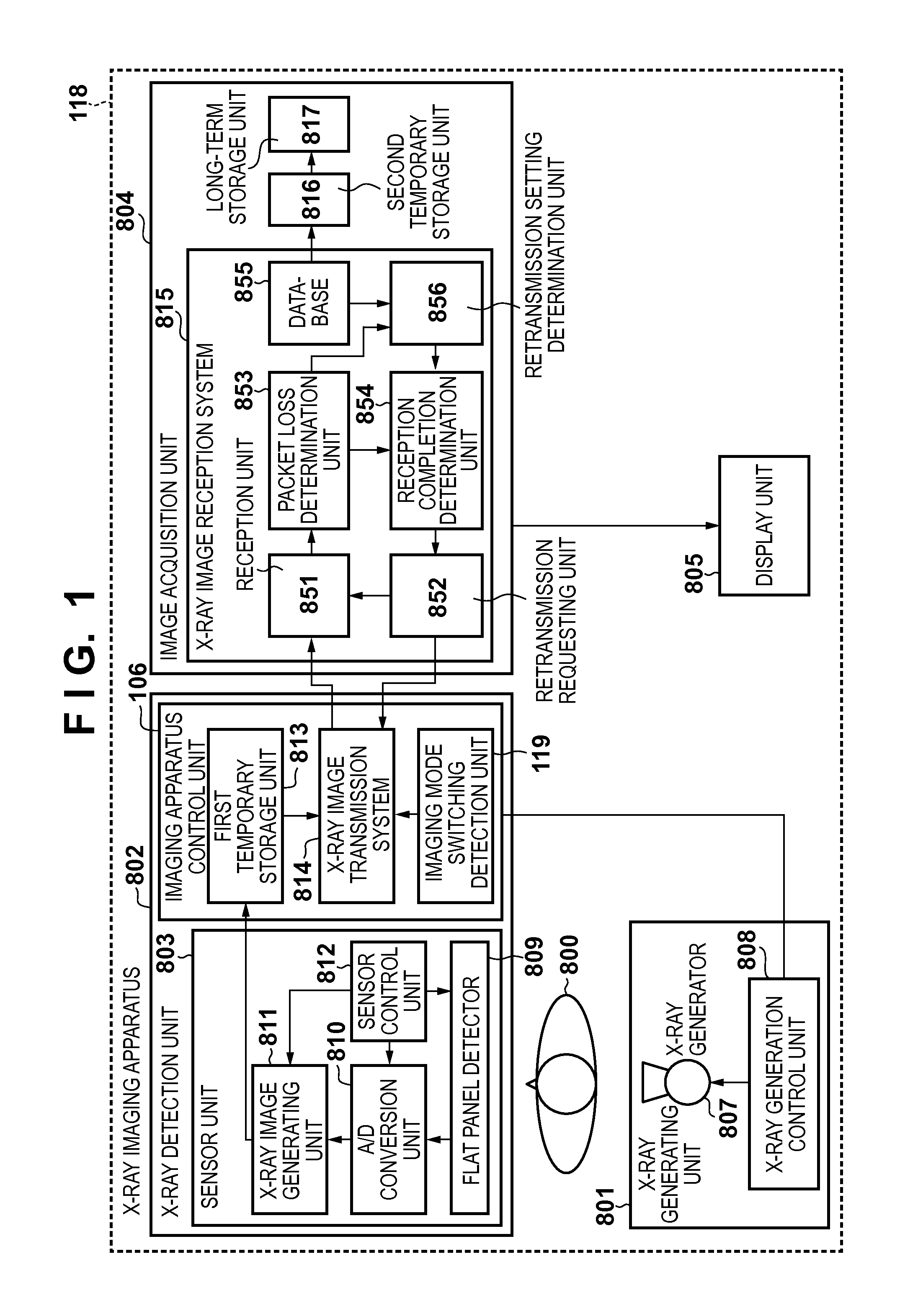
[0086]FIG. 1 shows an example of the arrangement of an X-ray imaging apparatus according to the second embodiment. The arrangement shown in FIG. 1 is the same as that in the first embodiment except that an imaging apparatus control unit 106 is used as an arrangement obtained by adding an imaging mode switching detection unit 119 to an imaging apparatus control unit 806 in the arrangement in FIG. 8. The imaging mode switching detection unit 119 determines whether the imaging modes have been switched, and notifies an X-ray image transmission system 814 of the determination result. Note that only portions different from the first embodiment will be described, and any points to which no particular reference is made are the same as in the first embodiment.
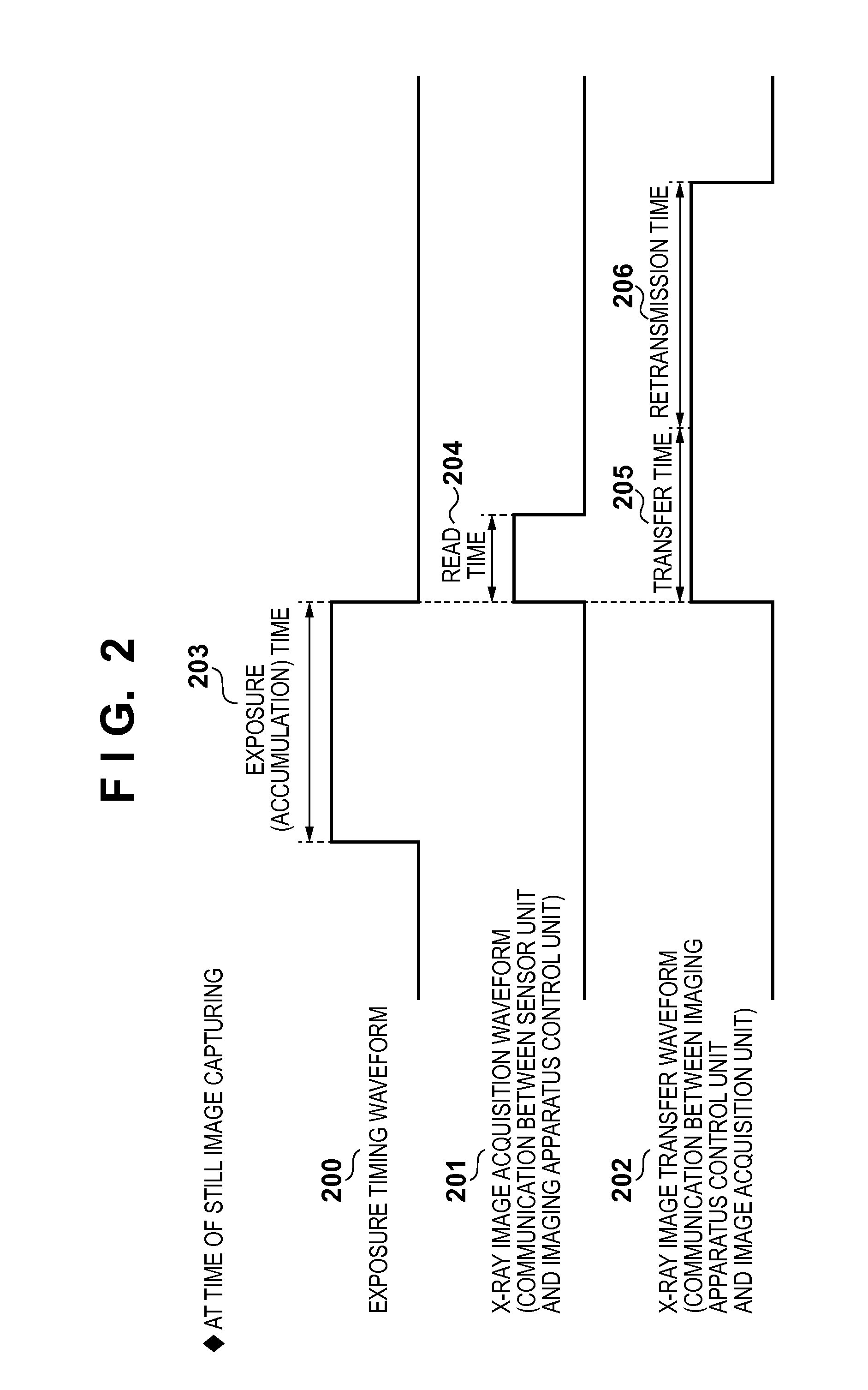
[0087]The operation of an X-ray imaging apparatus 118 which performs X-ray imaging while switching the imaging modes in the same manner as that shown in FIG. 5 will be described next with reference to FIG. 6. Referring to FIG. 6, like F...
third embodiment
[0091]In addition to the arrangement of the second embodiment, the third embodiment is configured to determine, upon detecting imaging mode switching via a imaging mode switching detection unit 119, whether the imaging mode after the switching operation is the still image mode or the moving image mode.
[0092]Upon determining that the imaging mode after the switching operation is the imaging mode of quickly performing imaging, the embodiment sets a retransmission time 608. On the other hand, upon determining that the imaging mode after the switching operation is the imaging mode which is not required to quickly perform imaging, the embodiment sets a normal retransmission time 607.
[0093]This arrangement can ensure the sufficient retransmission time 607 except when the imaging mode is switched to the imaging mode of quickly performing imaging. This makes it possible to reduce a deterioration in image quality due to a transfer error as compared with the second embodiment.
PUM
 Abstract
Description
Claims
Application Information
 - R&D
- Intellectual Property
- Life Sciences
- Materials
- Tech Scout
- Unparalleled Data Quality
- Higher Quality Content
- 60% Fewer Hallucinations
Browse by: Latest US Patents, China's latest patents, Technical Efficacy Thesaurus, Application Domain, Technology Topic, Popular Technical Reports.
© 2025 PatSnap. All rights reserved.Legal|Privacy policy|Modern Slavery Act Transparency Statement|Sitemap|About US| Contact US: help@patsnap.com


