Echo cancellation

a technology of echo cancellation and noise cancellation, applied in the direction of electrical transducers, transducer types, low frequency amplifiers, etc., can solve the problems of difficult and uncomfortable listening experience of far-end talkers, and achieve the effect of increasing the magnitude of sound waves and reducing the output of sound waves

Inactive Publication Date: 2013-09-05
SONY MOBILE COMM INC
View PDF3 Cites 3 Cited by
  • Summary
  • Abstract
  • Description
  • Claims
  • Application Information

AI Technical Summary

Benefits of technology

[0026]In some embodiments, the microphone system, using output associated with the second transistor, reduces a magnitude of the sound waves output by the speaker system.
[0027]In some embodiments, the microphone system increases a magnitude of sound waves associated with a user's speech that are received at the membrane (e.g., sound waves associated with a user speaking in close proximity to the membrane).
[0028]In some embodiments, a method is provided for reducing echo associated with a microphone system. In some embodiments, the method comprises providing a microphone system comprising: a housing that at least partially encloses a cavity and an electrode; a moveable membrane configured to receive sound waves, the membrane and the electrode forming a capacitive electret element, the sound waves causing the movable membrane to move thereby resulting in a change in the capacitive electret element's capacitance; and a single semiconductor package comprising a first transistor connected to the capacitive electret element such that a change in the capacitive electret element's capacitance changes an amount of current flowing through the first transistor, and a second transistor not connected to the capacitive electret element.
[0033]In some embodiments, the code further causes a computer to configure the microphone system to reduce, using an output associated with the second transistor, a magnitude of the sound waves output by the speaker system that are received by the membrane.

Problems solved by technology

If the echo is not reduced, the far-end talker encounters a difficult and an uncomfortable listening experience, especially because of the delay after which the echo can be heard.

Method used


Image

  • Echo cancellation
  • Echo cancellation
  • Echo cancellation

Examples


Embodiment Construction

[0045]Embodiments of the present invention now may be described more fully hereinafter with reference to the accompanying drawings, in which some, but not all, embodiments of the invention are shown. Indeed, the invention may be embodied in many different forms and should not be construed as limited to the embodiments set forth herein; rather, these embodiments are provided so that this disclosure may satisfy applicable legal requirements. Like numbers refer to like elements throughout.

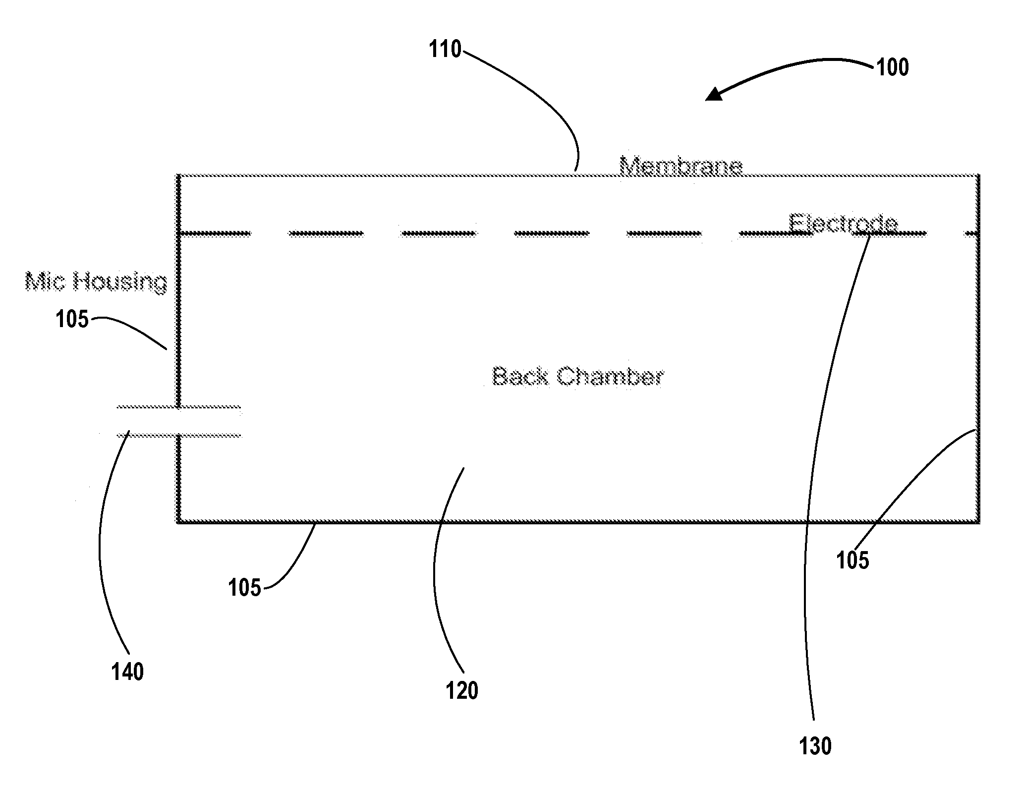
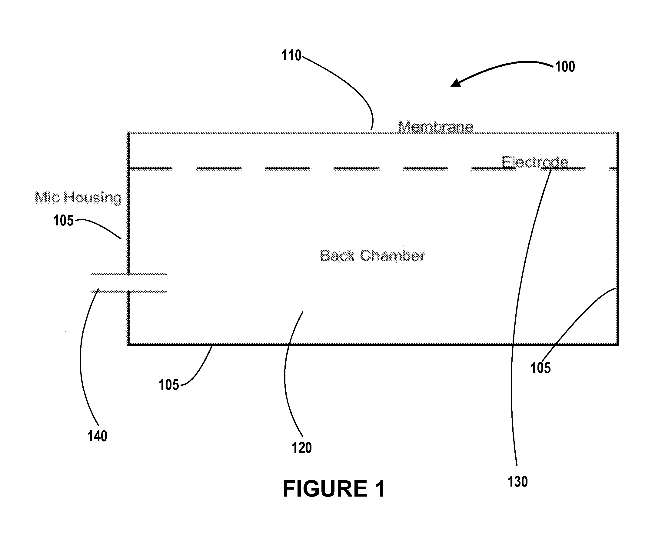
[0046]Echo cancellation includes the process of identifying and reducing the magnitude or level of speaker output that re-appears (e.g., with a delay, with modified frequencies, etc.) in microphone input. As used herein, echo comprises the sound waves output by the speaker that are received at the microphone (e.g., a membrane associated with the microphone). When this speaker output is identified, this speaker output may be subtracted or removed from the microphone input. The speaker and microphone ma...


PUM


Abstract

The invention is directed to echo cancellation for a microphone system. An exemplary microphone system comprises a first transistor, wherein a gate terminal of the first transistor is connected to a ground terminal via a microphone electret element, the microphone electret element being associated with a capacitance and a voltage, the microphone electret element reverse biasing the first transistor; and a second transistor in parallel with the first transistor, wherein a gate terminal of the second transistor is connected to the ground terminal via a capacitor, the capacitance of the capacitor being selected to suppress at least a portion of a common mode signal, and wherein the gate terminal of the second transistor is not connected to the microphone electret element. The common mode signal comprises the echo, which may be the output of a speaker system that is received as input to the microphone system.

Description

BACKGROUND[0001]Echo arises when audio from a speaker is picked by a microphone situated nearby. When a speaker and a microphone are being used for telecommunication, the echo can be heard by a far-end talker. A near-end talker may be a user of the speaker and the microphone, while a far-end talker is anyone who uses a communication device (e.g., a portable mobile communication device) to communicate with the user of the speaker and microphone. If the echo is not reduced, the far-end talker encounters a difficult and an uncomfortable listening experience, especially because of the delay after which the echo can be heard.[0002]The echo arises when the microphone and the speaker are part of the same device or when the microphone and the speaker are part of different devices but are situated closed to each other. Echo arises even when the microphone and speaker are not situated close to each other, but the audio output of the speaker is received by or is picked up by the microphone. Ex...

Claims


Application Information

Patent Timeline
Patent Type & Authority Applications(United States)
IPC IPC(8): H04B3/20H04R3/00
CPCH04R3/02H04R19/016H03F2200/03H03F3/185H03F2203/45082H03F2203/45084H03F2203/45088H03F2203/45076
Inventor ERIKSSON, JOAKIMSTRANDH, JONNY
Owner SONY MOBILE COMM INC
Why Eureka
Try Eureka