Aircraft landing gear

Active Publication Date: 2013-09-12
MESSIER DOWTY
View PDF6 Cites 13 Cited by
  • Summary
  • Abstract
  • Description
  • Claims
  • Application Information

AI Technical Summary

Benefits of technology

[0024]According to a third aspect of the present invention, there is provided an aircraft landing gear including a strut having an upper portion arranged to be coupled to the underside of an aircraft and a lower portion telescopically mounted with respect to the upper portion; a bogie including a bogie beam pivotally coupled to the lower portion of the main strut, the bogie beam having a plurality of axles mounted on it, each axle carrying one or more wheel assemblies; a linkage including a first coupling region via which it is pivotally coupled to the bogie and a second coupling region by which it is pivotally coupled to the main strut, the linkage being arranged such that its effective length can be changed so as to cause a change in the angular position of the bogie relative to the strut, the linkage including an actuator; wherein the aircraft landing gear includes or is in combination with a control device operable to a configuration in which the control device is arranged to reduce loads experienced by components of the actuator during taxiing.
[0025]Thus, upon detecting that the aircraft has touched down the control device permits the effective length of the linkage to vary. This is advantageous because, as noted above, a known landing gear pitch trimming actuator provides a hydraulic damping function that damps pivoting movements of the bogie as it engages bumps or dips in the runway. Thus, one of

Problems solved by technology

Thus, upon detecting that the aircraft has touched down the control valve reduces the pressure of the control fluid supplied to the port, which reduces the operating pressure and thus the damping ratio for the actuator.
For some prior art landing gears, results in the actuator experiencing numerous forces that are short in duration, yet large magnitude.
During ground manoeuvring, a continuous positioning force is provided to the bogie, which results in the dynamic glan

Method used


Image

  • Aircraft landing gear
  • Aircraft landing gear
  • Aircraft landing gear

Examples


Embodiment Construction

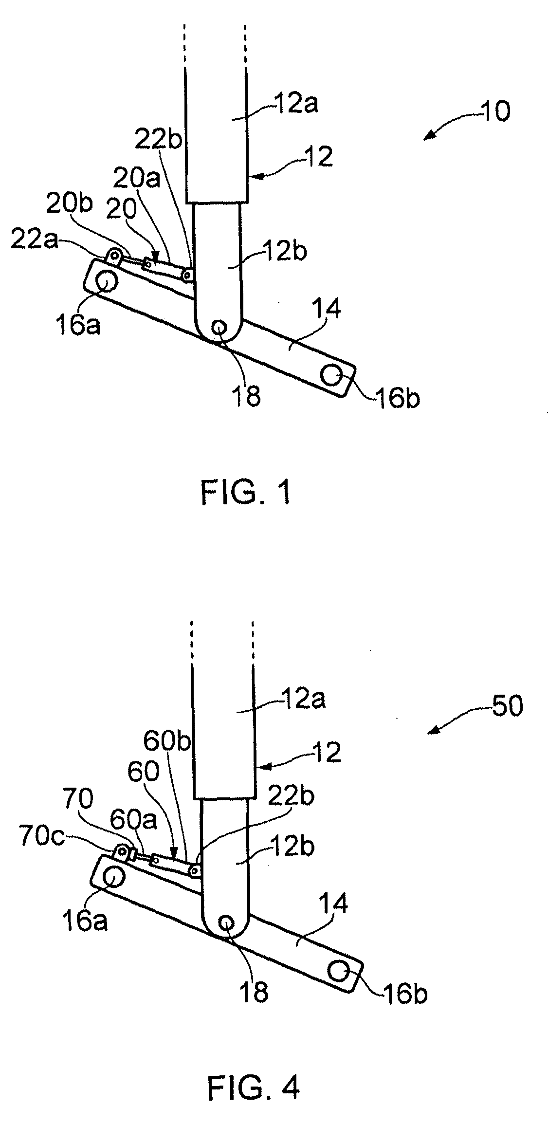
[0044]FIG. 1 shows a partial, schematic side view of a landing gear 10 according to a first embodiment of the present invention. The landing gear 10 includes a main strut 12, having an upper portion 12a arranged to be coupled to the underside of an aircraft (not shown) and a lower portion 12b telescopically mounted with respect to the upper portion 12a. A bogie beam 14 is pivotally coupled to the lower portion of the main strut 12b, the bogie beam 14 having first and second axles 16a, 16b mounted on it, each axle 16a, 16b carrying one or more wheel assemblies (not shown). A landing gear according to embodiments of the present invention may have any suitable number of axles and wheels per axle.

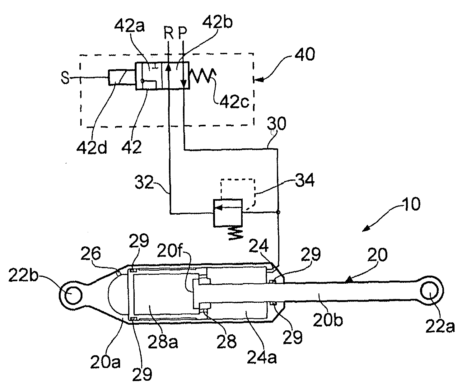
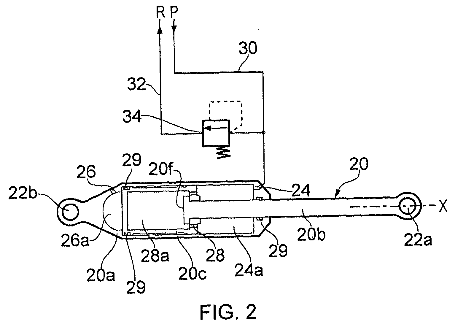
[0045]A linkage 20 is pivotally coupled to the bogie beam 14 at a first coupling region 22a and pivotally coupled to the lower strut portion 12b at a second coupling region 22b. In the illustrated embodiment the linkage is defined by an actuator 20. As will be appreciated, pivotal movement of t...


PUM


Abstract

An aircraft landing gear including: a main strut having an upper portion arranged to be coupled to the underside of an aircraft and a lower portion telescopically mounted with respect to the upper portion; a bogie including a bogie beam pivotally coupled to the lower portion of the main strut, the bogie beam having a plurality of axles mounted on it, each axle carrying one or more wheel assemblies; an actuator arranged such that a change in its effective length causes a change in the angular position of the bogie relative to the main strut, and a control port arranged to be coupled to a control fluid supply system, wherein the aircraft landing gear includes or is in combination with a control valve having a first configuration in which it permits control fluid to be supplied to the control port of the actuator at a first pressure and a second configuration in which the control valve permits the supply of control fluid to the control port at a second pressure less than the first pressure so as to reduce loads experienced by components of the actuator during taxiing.

Description

BACKGROUND OF THE INVENTION[0001]A typical landing gear comprises a main strut having an upper portion adapted to be connected to the underside of the aircraft and a lower portion telescoping within the upper portion and pivotally connected to a bogie. The bogie comprises a bogie beam with axles and wheels mounted on the bogie beam fore and aft of a main pivot by which the bogie beam is connected to the lower portion of the main strut.[0002]The main strut can be moved between a deployed position, for ground manoeuvring take off and landing, and a stowed position, for flight. When in the stowed position both the strut and bogie are contained within a landing gear cavity in the aircraft. The bogie beam must be within a range of angular positions with respect to the strut to enable the landing gear to be stowed in the cavity without striking the aircraft fuselage. The angular position or “pitch” of the bogie beam relative to the strut required for stowing is known in the art as its “tr...

Claims


Application Information

Patent Timeline
IPC IPC(8): B64C25/20B64C25/22
CPCB64C25/34B64C2025/008B64C25/22B64C25/20B64C2025/345B64C25/26
Inventor GOODBURN, SIMONCHISHOLM, GLENNELL, SAM
Owner MESSIER DOWTY
Why Eureka
Try Eureka