Irradiation device

a technology of irradiation device and infrared emitter, which is applied in the direction of incandescent vessel seal, nuclear engineering, therapy, etc., can solve the problems of limiting the service life of infrared emitter and its output, complicated production, and disadvantages of pinched sections, and achieves high and efficient energy application.

Inactive Publication Date: 2013-09-12
HERAEUS NOBLELIGHT GMBH
View PDF27 Cites 7 Cited by
  • Summary
  • Abstract
  • Description
  • Claims
  • Application Information

AI Technical Summary

Benefits of technology

[0065]A mount for a substrate to be irradiated in the interior chamber of the irradiation device allows a direct irradiation of the substrate without the in-between arrangement of a material that absorbs infrared radiation and has the advantage that the distance between the infrared emitter and the substrate can be selected as small as possible. Both promote a high

Problems solved by technology

Pinched sections are basically disadvantageous.
They are complicated to produce, and they limit the service life of the infrared emitter and its output, as discussed in more detail below.
In practice, it is difficult to set up the metallic components of the pinched section, that is, the two-sided connection pins and the metal film, exactly flush or to fix the metal pin going outward exactly in the middle.
This makes space-saving, precise mounts or contacts for such emitters difficult.
In irradiation devices there is often the problem of sealing the interior chamber from the surroundings, for example if a high temperature or a pressure difference must be maintained in the interior chamber or if there are gases or liquids in the interior chamber that should not escape into the surroundings.
This makes other problems noticeable due to the pinching.When shaping the pinched section, this section is wider than the outer diameter of the quartz glass tube.
This effect can indeed be avoided if a higher degree of deformation of the quartz glass tube can be accepted, but this leads to a higher reject rate in production.
Therefore, the deformed area of the quartz glass tube cannot enter into the reactor space, which means a loss of ef

Method used


Image

  • Irradiation device
  • Irradiation device
  • Irradiation device

Examples


example 1

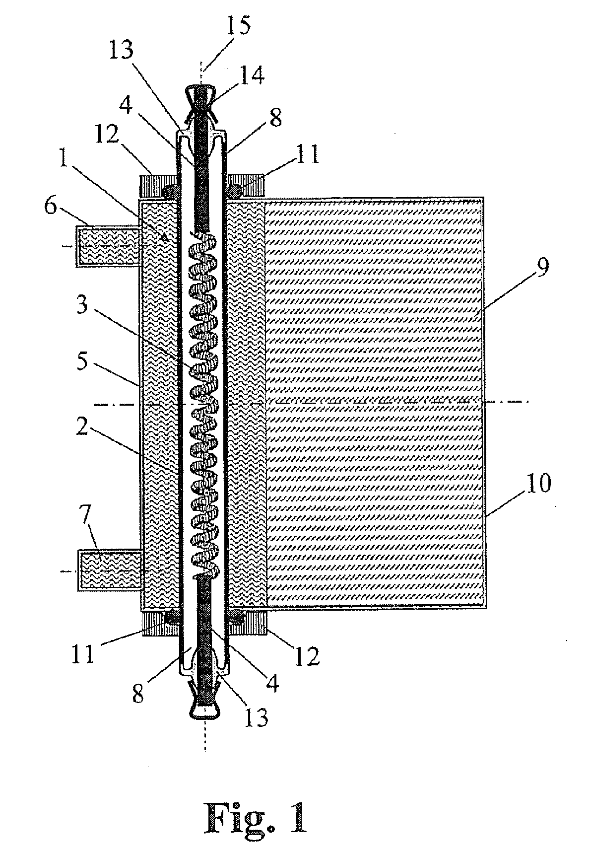
[0071]FIG. 1 shows schematically a handheld irradiation device for cosmetic purposes. It is equipped with an infrared emitter 1, wherein this involves a shortwave IR emitter having a nominal power of 250 W.

[0072]The infrared emitter 1 has an axially symmetrical emitter tube 2 made of quartz glass having a round cross section and an outer diameter of 10 mm and a length of 100 mm. The ends of the emitter tube 2 are not deformed and have the same cross section and diameter as the middle part of the emitter tube 2.

[0073]The emitter tube 2 encloses an interior chamber gas-tight, wherein a coil-shaped heating filament 3 made of tungsten having a (heated) length of 50 mm is arranged in this interior chamber and this interior chamber is filled with argon (without halogen additives). The ends of the heating coil 3 are each welded with a round electrical connection pin 4 having an outer diameter of 2 mm, also made of tungsten. The connection pins 4 are led out from opposing open end sides of ...

example 2

[0080]In general, there is only a limited space available for installations in the evacuated region. Indeed, bus bars can be placed in isolated or gas-filled, separate spaces. However, it is difficult to connect the emitters to these bus bars, such that no sparkovers are produced. The gaps of the seal must also be designed with very tight tolerances, in order to prevent the penetration of sparkovers or the formation of surface discharges.

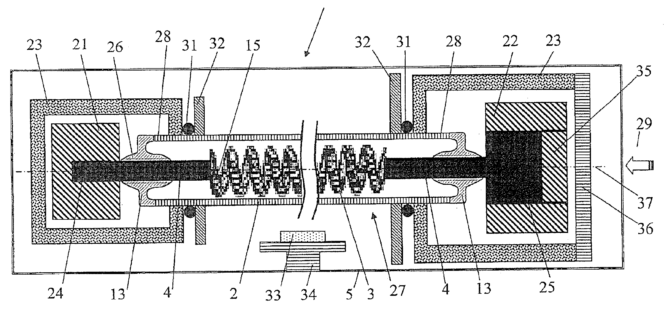
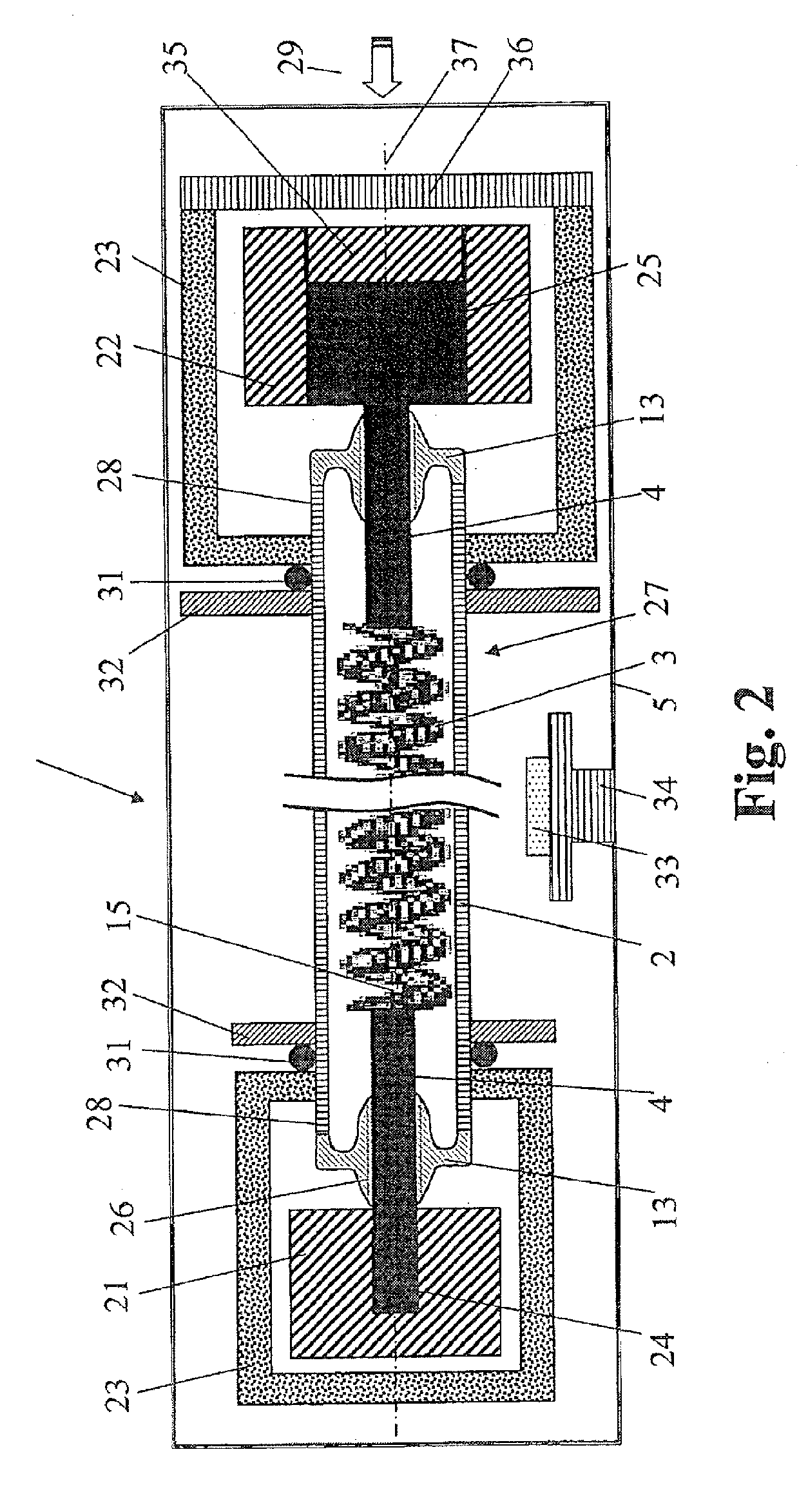
[0081]FIG. 2 shows schematically a vacuum irradiation device for a rough vacuum and a fine vacuum, having a vacuum chamber 20, in which two bus bars 21, 22 are arranged in pairs. These are each provided with a sheathing 23 made of non-conductive, heat-resistant plastic, which prevents sparkovers between the bus bars 21, 22 and the surroundings.

[0082]In the sheathing 23 openings are formed, through each of which exactly one emitter tube 2 passes, wherein the bus bars 21, 22 lying in the interior of the sheathing 23 also have, axial to the opening, a ...


PUM


Abstract

An irradiation device is provided having a housing having an interior chamber and an infrared emitter arranged therein. The infrared emitter has an emitter tube made of high silica content glass having a round cross section and a defined outer diameter. Electrical connection elements are made of a metallic material and led out from the emitter tube through a seal. In order to provide the emitter with a long service life and potentially higher output, which is also suitable for being enclosed by a seal that separates the regions of different media, temperatures, or pressures, the emitter tube end also has a round cross section and the defined outer diameter. Between the electrical connection element and the emitter tube there is a seal containing at least one transition glass, which has a thermal expansion coefficient lying between that of the metallic material and that of the high silica content glass.

Description

CROSS-REFERENCE TO RELATED APPLICATIONS[0001]This application is a Section 371 of International Application No. PCT / EP2011 / 005494, filed Oct. 31, 2011, which was published in the German language on May 24, 2012, under International Publication No. WO 2012 / 065688 A3 and the disclosure of which is incorporated herein by reference.BACKGROUND OF THE INVENTION[0002]The invention relates to an irradiation device comprising a housing having an interior chamber and an infrared emitter arranged in this interior chamber. The emitter has an emitter tube made of a high silica content glass and has a circular cross section and defined outer diameter. A ribbon- or coil-shaped heating filament is arranged in the emitter tube and provided with electrical connection elements made of a metallic material and guided out from the emitter tube via a seal. At least one of the emitter tube ends extends into an outer space separated in a fluid-tight manner from the interior chamber by a sealing element cont...

Claims


Application Information

Patent Timeline
IPC IPC(8): B01J19/12
CPCH01K1/38H01K3/20H05B3/0038H01K7/00B01J19/128H01J5/14H01K1/36H05B3/44
Inventor LINOW, SVEN
Owner HERAEUS NOBLELIGHT GMBH
Why Eureka
Try Eureka