Apparatus for transferring energy using onboard power electronics and method of manufacturing same

a technology of power electronics and equipment, applied in the direction of electric devices, charging stations, transportation and packaging, etc., can solve the problems of adding additional dedicated components, adding extra cost and weight to the vehicle,

Active Publication Date: 2013-09-12
GENERAL ELECTRIC CO
View PDF11 Cites 56 Cited by
  • Summary
  • Abstract
  • Description
  • Claims
  • Application Information

AI Technical Summary

Benefits of technology

[0006]According to an aspect of the invention, an apparatus comprises a first energy storage device configured to output a DC voltage and a DC bus coupled to the first energy storage device, the DC bus coupleable to a high-impedance voltage source. The apparatus also comprises a braking resistor coupled to the DC bus and to a control circuit, and a controller. The controller is configured to control the control circuit to cause on the DC bus to be dissipated through the braking resistor during a regenerative braking event, cause the first energy storage device to receive a charging energy from the high-impedance voltage source through the braking resistor during a charging event, and after a threshold value has been crossed, cause the first energy storage device to receive the charging energy from the high-impedance voltage source bypassing the braking resistor during the charging event.
[0007]According to another aspect of the invention, a method of fabricating an energy transfer system for transferring energy between an energy storage device on-board a vehicle and an external source comprises coupling the energy storage device to a voltage bus, the energy storage device configured to output a DC voltage, coupling a regenerative braking dissipation circuit to the voltage bus, and coupling a high-impedance voltage source to the voltage bus to supply current to the energy storage device. The method also comprises configuring a controller to cause the control circuit to dissipate energy on the voltage bus through a resistor of the regenerative braking dissipation circuit during a regenerative braking event, cause the first energy storage device to receive the current from the high-impedance voltage source via the resistor during a first stage of a charging event, and cause the first energy storage device to receive the current from the high-impedance voltage source bypassing the resistor during a second stage of the charging event.

Problems solved by technology

These additional dedicated components add extra cost and weight to the vehicle.

Method used


Image

  • Apparatus for transferring energy using onboard power electronics and method of manufacturing same
  • Apparatus for transferring energy using onboard power electronics and method of manufacturing same
  • Apparatus for transferring energy using onboard power electronics and method of manufacturing same

Examples


Embodiment Construction

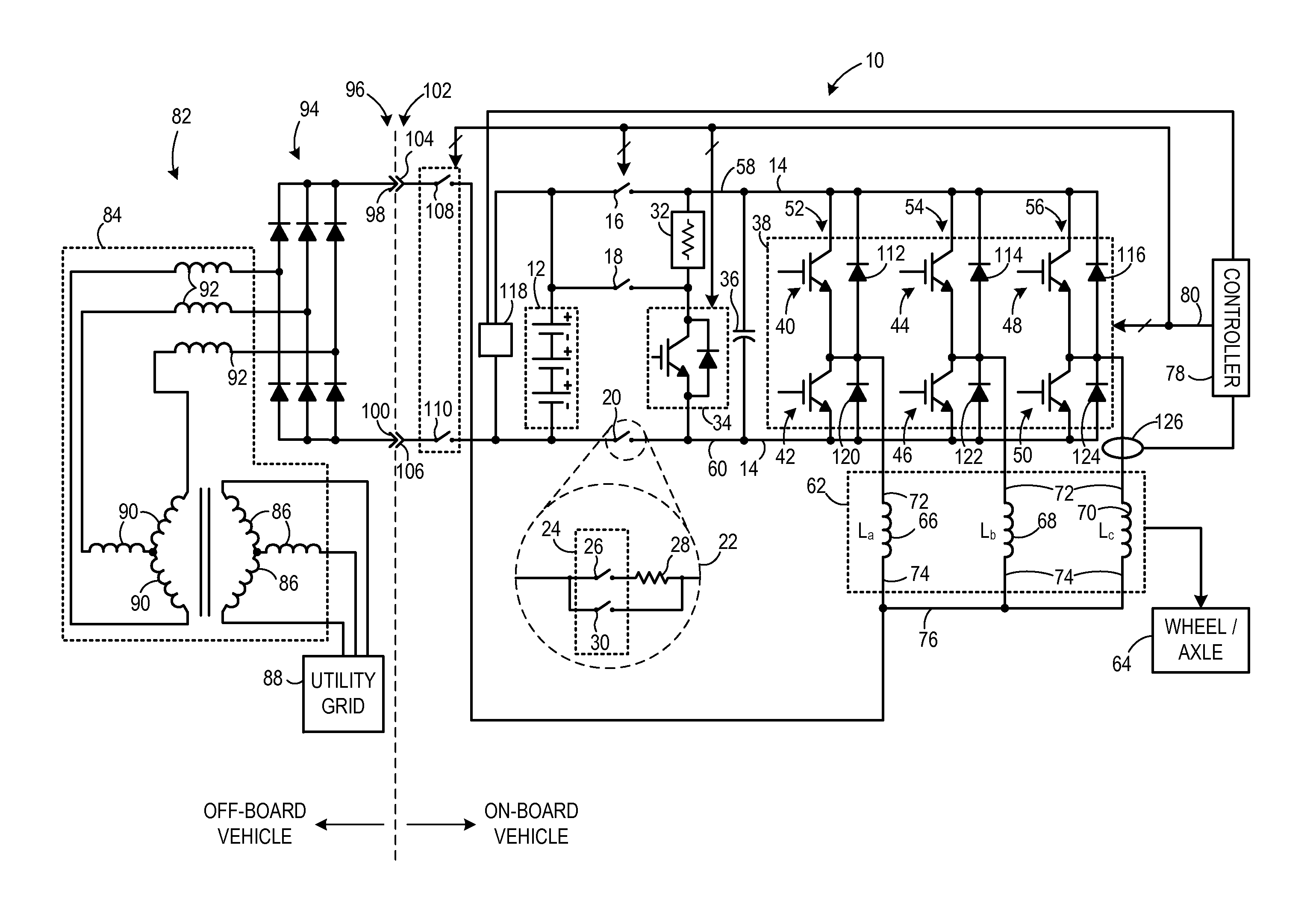
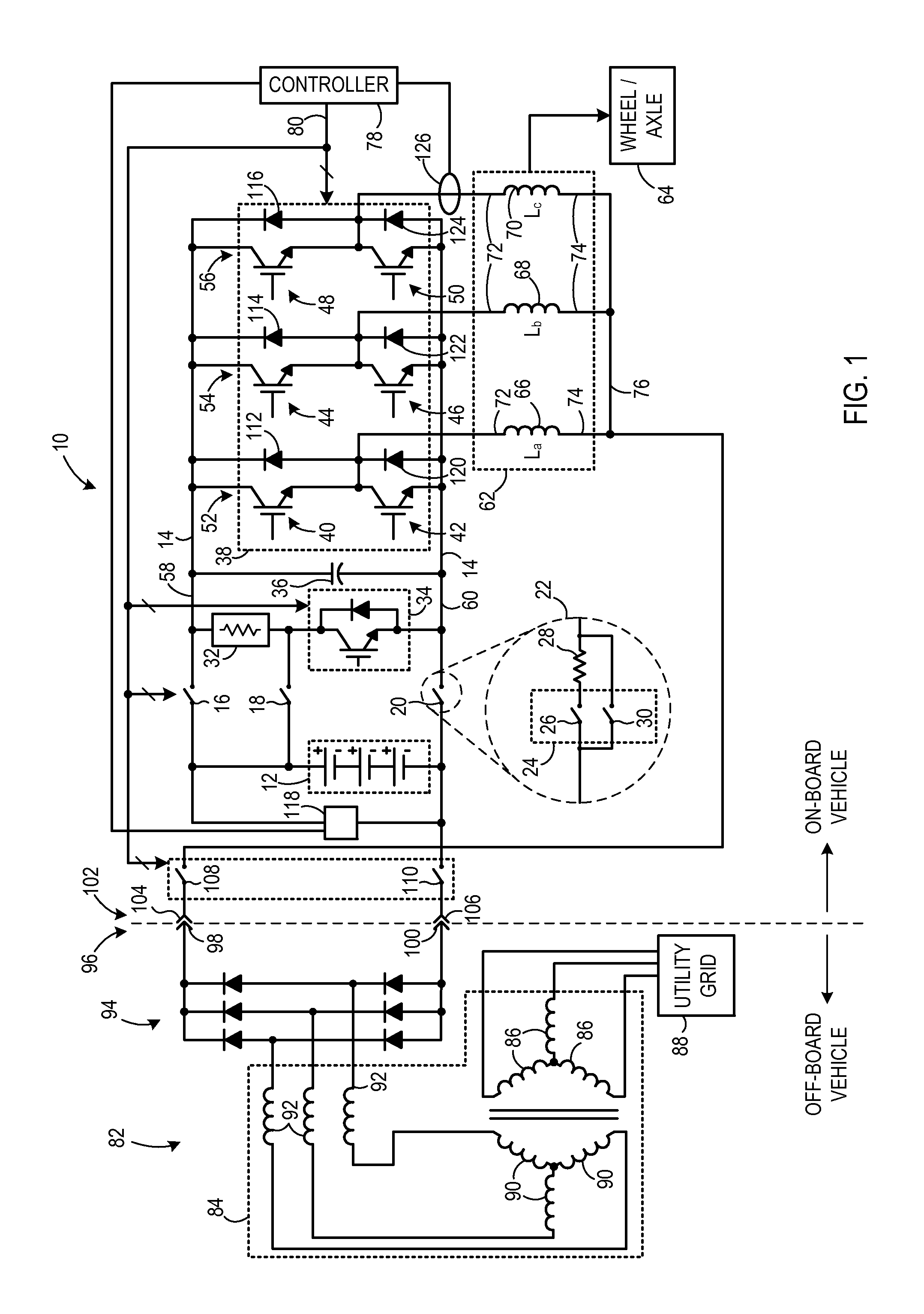
[0016]FIG. 1 is a schematic diagram of a traction system 10 according to an embodiment of the invention. Traction system 10 includes a first energy storage device 12. In one embodiment, first energy storage device 12 is a high-voltage energy storage device and may be a battery, a flywheel system, fuel cell, an ultracapacitor, or the like. First energy storage device 12 is coupleable to a DC link or bus 14 via an array of contactors or switches 16, 18, 20. As described below, switches 16-20 are controlled during operation of traction system 10 in a motoring mode and in a recharging mode.

[0017]In one embodiment as shown in further detail at 22, switch 20 may include a switch array 24 coupled between first energy storage device 12 and DC bus 14. Switch array 24 includes a first switch 26 coupled in series with a pre-charge resistor 28. A second switch 30 is coupled in parallel with first switch 26 and pre-charge resistor 28. When switch 26 is closed and switch 30 is open, current flowi...


PUM


Abstract

An apparatus for transferring energy using onboard power electronics comprises a first energy storage device configured to output a DC voltage and a DC bus coupled to the first energy storage device, the DC bus coupleable to a high-impedance voltage source. The apparatus also comprises a braking resistor coupled to the DC bus and to a control circuit, and a controller. The controller is configured to control the control circuit to cause on the DC bus to be dissipated through the braking resistor during a regenerative braking event, cause the first energy storage device to receive a charging energy from the high-impedance voltage source through the braking resistor during a charging event, and after a threshold value has been crossed, cause the first energy storage device to receive the charging energy from the high-impedance voltage source bypassing the braking resistor during the charging event.

Description

BACKGROUND OF THE INVENTION[0001]Embodiments of the invention relate generally to electric drive systems including hybrid and electric vehicles and to stationary drives that are subject to transient or pulsed loads and, more particularly, to transferring energy between an electrical storage device of the vehicle or drive and a power source external to the vehicle or drive.[0002]Hybrid electric vehicles may combine an internal combustion engine and an electric motor powered by an energy storage device, such as a traction battery, to propel the vehicle. Such a combination may increase overall fuel efficiency by enabling the combustion engine and the electric motor to each operate in respective ranges of increased efficiency. Electric motors, for example, may be efficient at accelerating from a standing start, while combustion engines may be efficient during sustained periods of constant engine operation, such as in highway driving. Having an electric motor to boost initial acceleratio...

Claims


Application Information

Patent Timeline
Patent Type & Authority Applications(United States)
IPC IPC(8): H02J7/16
CPCY02T10/7005Y02T10/7022Y02T10/7033Y02T10/641Y02T90/14Y02T90/127Y02T10/92H02J7/022H02J7/041H02J7/045H02J7/1492B60L2220/54B60L11/1814Y02T10/7072B60L53/24H02J7/0071H02J2310/48H02J7/02H02J2207/20Y02T10/64Y02T10/70H02J7/04H02J7/007182Y02T90/12
Inventor KING, ROBERT DEANSTEIGERWALD, ROBERT LOUIS
Owner GENERAL ELECTRIC CO
Why Eureka
Try Eureka