
Zero voltage switching interleaved boost ac/dc converter

a technology of ac/dc converter and zero voltage, which is applied in the field of zero voltage switching interleave, can solve the problems of reducing the reliability of the converter, increasing the complexity of the system, and deteriorating the efficiency of the converter

Active Publication Date: 2013-09-12
SPARQ SYST INC
View PDF10 Cites 78 Cited by
  • Summary
  • Abstract
  • Description
  • Claims
  • Application Information

AI Technical Summary

Benefits of technology

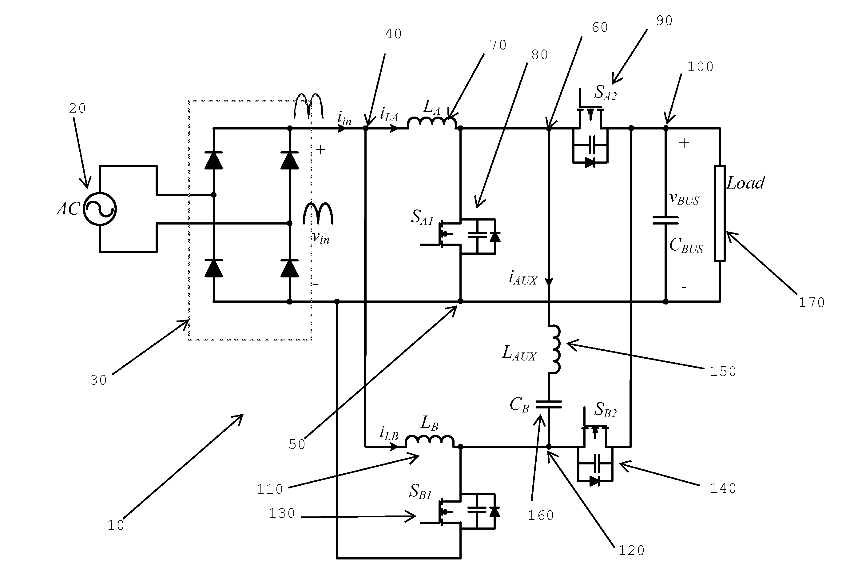
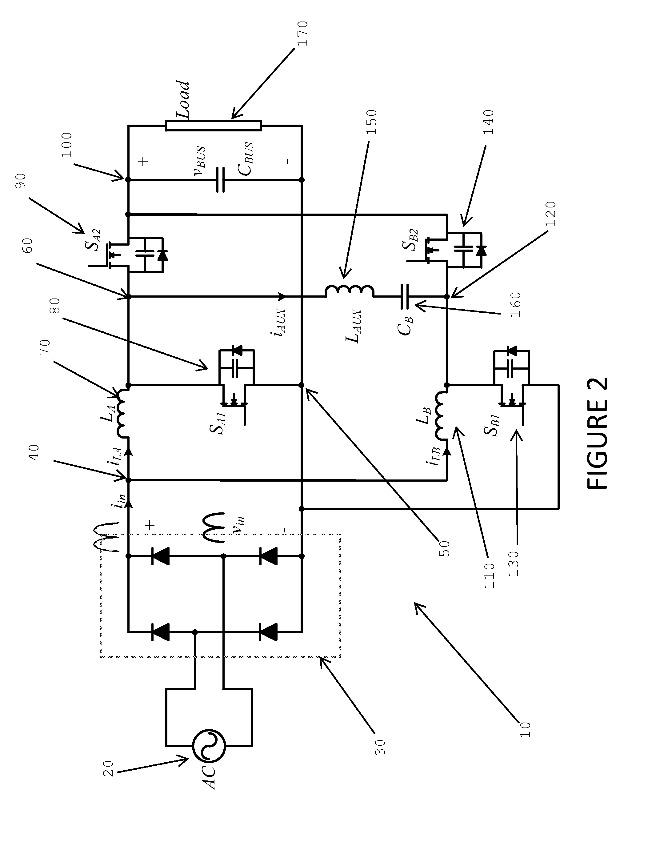
The present invention provides circuits and methods for ensuring zero voltage switching (ZVS) in a boost power factor correction converter. A simple passive circuit using a series connected inductor and capacitor are coupled between two phases of an interleaved boost PFC converter. A control system for adjusting and controlling the reactive current to ensure ZVS for different loads and line voltages is also provided. The technical effect of this invention is to improve the efficiency and reliability of power factor correction converters by ensuring ZVS, which reduces switching loss and increases the power conversion efficiency.

Problems solved by technology

Switching losses of the power switches in boost PFC AC / DC converters significantly deteriorate the efficiency of the converter.
Present products usually use active auxiliary circuits in order to provide soft-switching, which increases the complexity of the system while decreasing its reliability.
Loss of ZVS means extremely high switching losses at high switching frequencies and very high EMI.
Loss of ZVS can also cause a very noisy control circuit, which leads to shoot-through and loss of the semiconductor switches.

Method used


Image

  • Zero voltage switching interleaved boost ac/dc converter
  • Zero voltage switching interleaved boost ac/dc converter
  • Zero voltage switching interleaved boost ac/dc converter

Examples


Embodiment Construction

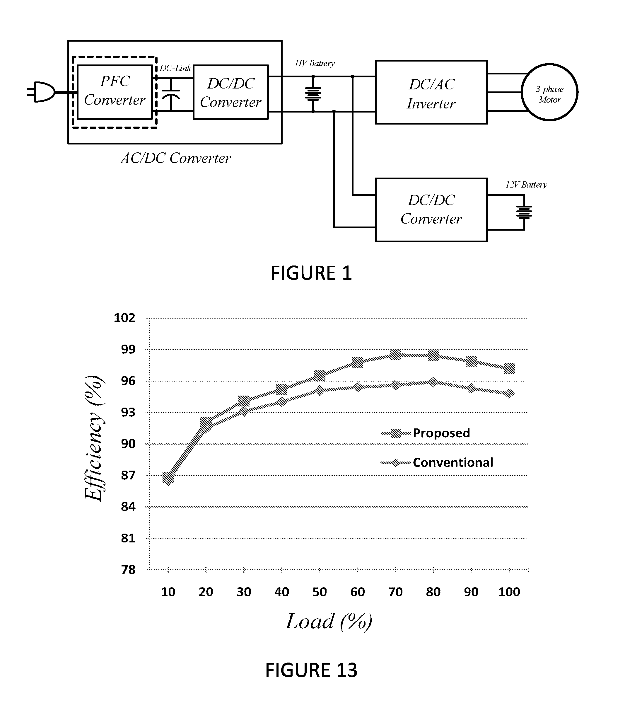
[0042]Referring to FIG. 1, a block diagram of a typical power conditioning system in an electric vehicle is illustrated. As can be seen, a wall plug is coupled to a PFC converter block which, in turn, is coupled to a DC / DC converter. The -PFC converter block and the DC / DC converter block, taken together, form the AC / DC converter block. The output of the AC / DC converter block is then received by a DC / DC converter and a DC / AC converter which, in turn, powers a 3 phase motor.

[0043]One aspect of the invention may be used in the PFC converter illustrated in FIG. 1. This aspect of the invention provides for a ZVS interleaved boost PFC AC / DC converter as described below. This aspect of the invention may be used in substantially any AC / DC converter application. It is, however, particularly useful in Electric Vehicle (EV) applications due to its superior performance and high efficiency. There are two main sources of losses in boost PFC converters: turn-on losses of the boost power switch and...


PUM


Abstract

Circuits and methods relating to the provision of a reactive current to ensure zero voltage switching in a boost power factor correction converter. A simple passive circuit using a series connected inductor and capacitor are coupled between two phases of an interleaved boost PFC converter. The passive circuit takes advantage of the 180° phase-shift between the two phases to provide reactive current for zero voltage switching. A control system for adjusting and controlling the reactive current to ensure ZVS for different loads and line voltages is also provided.

Description

TECHNICAL FIELD[0001]The present invention relates to circuits and power supplies. More specifically, the present invention relates to circuits and methods for use in AC / DC converters which can be used to ensure zero voltage switching.BACKGROUND OF THE INVENTION[0002]The ever growing popularity of environmentally friendly or “green” products and services has led to a renewed interest in the electric car. While the practical, fully electric powered car might still be a few years in the future, its cousin, the hybrid car is already being used by the general public. Both these types of vehicles have their batteries usually recharged by plugging into regular 120V or 220V wall sockets. Developments that affect battery charging systems would therefore have a great impact on these types of vehicles.[0003]Electric Vehicle (EV) power conditioning systems usually utilize a high energy battery pack to store energy for the electric traction system. A typical block diagram of the power condition...

Claims


Application Information

Patent Timeline
Patent Type & Authority Applications(United States)
IPC IPC(8): H02M1/42
CPCH02M1/42H02M1/4225Y02B70/126Y02B70/12H02M3/1584Y02B70/10
Inventor PAHLEVANINEZHAD, MAJIDJAIN, PRAVEEN
Owner SPARQ SYST INC
Learn More