
Intraocular pressure modification

a technology of intraocular pressure and modification, applied in the field of ocular treatments, can solve the problems of patient compliance, reluctance to take long-term medications, and difficulty in getting drops in the ey

Active Publication Date: 2013-09-12
BERDAHL JOHN
View PDF14 Cites 56 Cited by
  • Summary
  • Abstract
  • Description
  • Claims
  • Application Information

AI Technical Summary

Benefits of technology

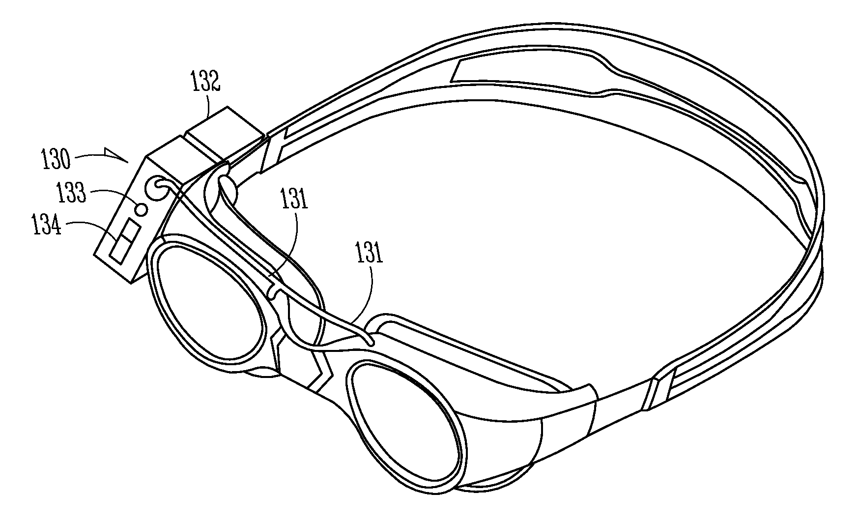
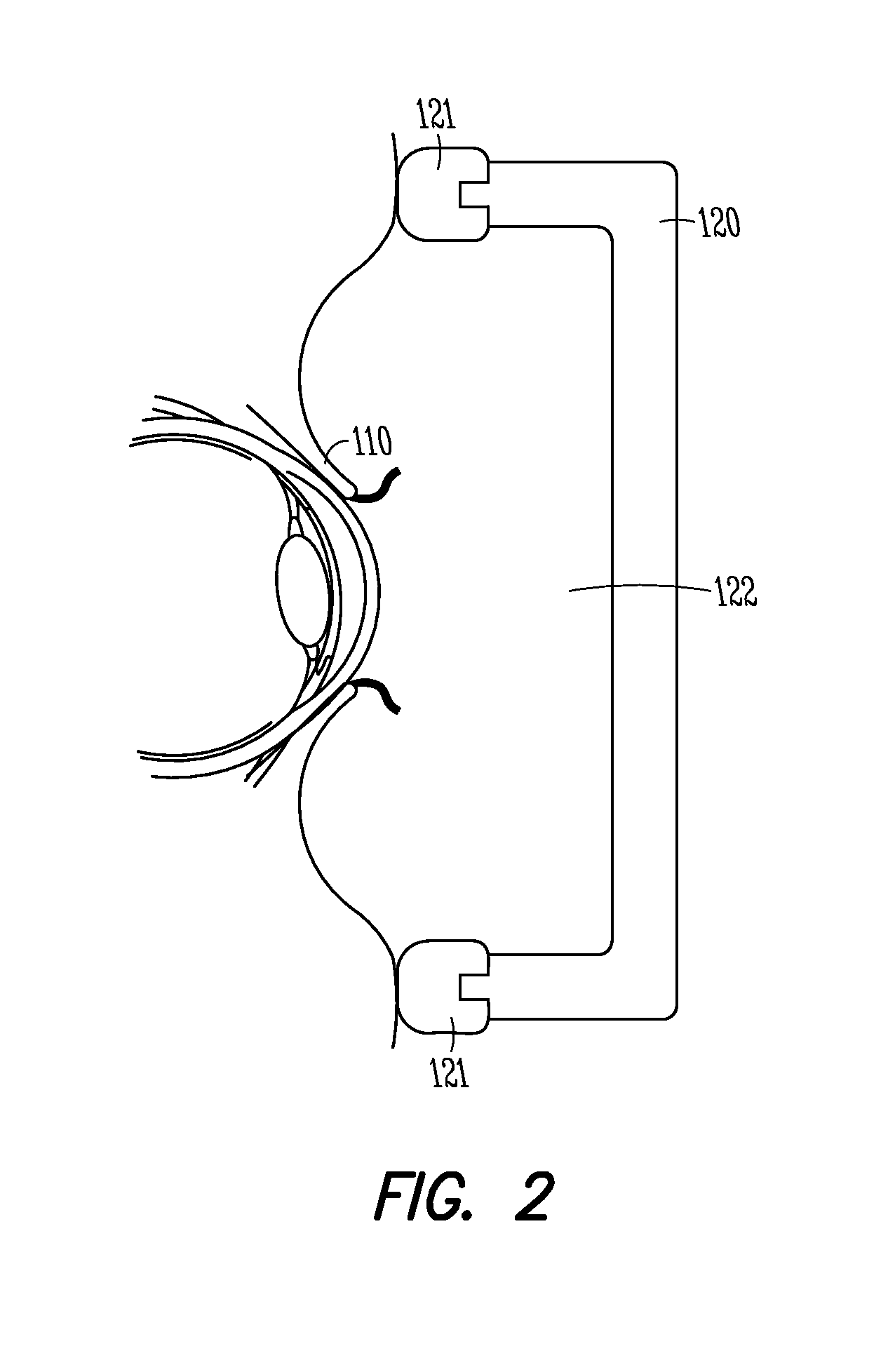
This patent describes an assembly for reducing intraocular pressure in patients with glaucoma or other optic nerve conditions. The assembly includes a goggle or goggles that can be placed over the patient's eyes to create a seal and maintain pressure inside the goggle. The pressure inside the goggle can be adjusted using a portable pump, such as a battery-powered pump, to control the air pressure over the eye. The assembly can be worn during the day or night, and the pressure modulation can be adjusted based on the condition being treated. The temporary reduction in intraocular pressure can improve axonal transport and lead to improved vision outcomes even after the goggle is removed.

Problems solved by technology

There is also a significant problem with patient compliance in taking eye drop medication on a regular basis.
Since glaucoma is a chronic condition and is not currently curable, glaucoma patients need to take their eye drop medication for the rest of their lives.
This failure can be due to forgetting, difficulty getting the drops in one's eyes, reluctance to take long-term medications, or unhappiness with certain side effects (e.g., redness of the eyes, eyelash growth, inflammation, orbital fat atrophy, discoloration of the iris or surrounding periorbital tissues, exacerbation of COPD or asthma, inhibition of corneal endothelial pump function, exacerbation of corneal edema, or stinging upon instillation).
This need is due to issues associated with eye drop medication compliance, the significant number of patients for whom eye drop medication is ineffective, and complication and morbidity rates of surgery.

Method used


Image

  • Intraocular pressure modification
  • Intraocular pressure modification
  • Intraocular pressure modification

Examples


Embodiment Construction

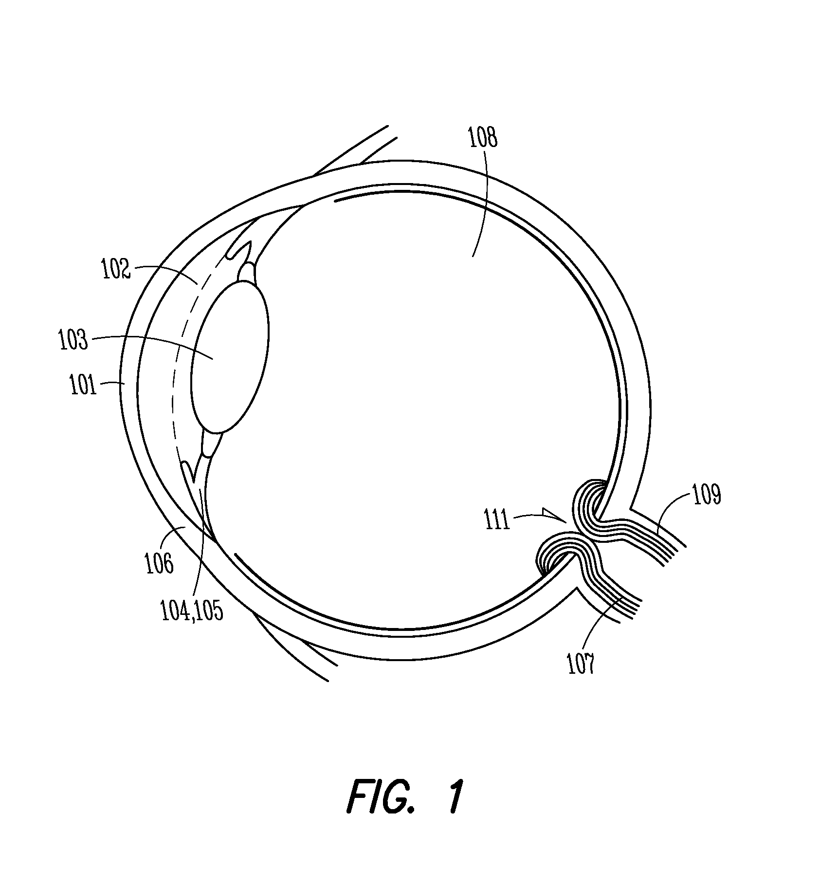
[0020]FIG. 1 illustrates ocular structures in cross-section, which provide a suitable environment for using the present assemblies and methods. A front surface of an eye is a cornea 101. Located behind the cornea 101 is an anterior chamber or aqueous chamber 102. This is the primary reservoir of aqueous humor inside the eye. Located behind the anterior chamber 102 is a lens 103, and behind and around the lens 103 are ciliary processes 105. The ciliary processes 105 are areas of the eye where aqueous humor is produced. The ciliary muscle 104 is roughly in the same plane as the lens 103 and is positioned around the perimeter of the lens 103. A trabecular meshwork 106, Schlemm's canal, and anterior ciliary veins are all located below the anterior chamber 102 at the bottom of the cornea 101. This is the primary pathway for aqueous humor to exit the eye.

[0021]Behind the lens 103 and the ciliary processes 105 is the posterior chamber of the eye filled with viscous humor 108. The viscous h...


PUM


Abstract

Assemblies and methods for modifying an intraocular pressure of a patient's one or both eyes are disclosed. The assemblies and methods can be used to treat, inhibit, or prevent ocular conditions such as glaucoma, high intraocular pressure, optic disc edema, idiopathic intracranial hypertension, zero-gravity induced papilledema, and other optic pressure related conditions. An assembly can include a goggle including at least one cavity, a pump in fluid communication with the at least one cavity, and a control mechanism. The control mechanism can be operatively coupled to the pump and can maintain a target pressure or target pressure range in the at least one cavity, which, when the assembly is worn by a patient, is the area between a patient's eye(s) and wall surfaces of the goggle. Controlling the pressure over the outer surfaces of the patient's eye(s) can drive a desired change in the intraocular pressure of the eye(s).

Description

CLAIM OF PRIORITY[0001]This non-provisional patent application claims the benefit of priority under 35 U.S.C. §119(e) to U.S. Provisional Patent Application Ser. No. 61 / 609,078, entitled “INTRAOCULAR PRESSURE MODIFICATION,” (Attorney Docket No. 3613.001PRV), filed on Mar. 9, 2012, which is hereby incorporated by reference in its entirety.TECHNICAL FIELD[0002]This patent document pertains generally to ocular treatments. More particularly, but not by way of limitation, this patent document pertains to modifying an intraocular pressure of a patient's one or both eyes.BACKGROUND[0003]Glaucoma is a common chronic condition predominantly affecting members of the elderly population. Glaucoma is a top cause of blindness worldwide and it is the leading cause of irreversible blindness worldwide. While glaucoma is not reversible, its progression can be stopped or slowed with treatment. Most existing glaucoma treatments fall into one of two categories: eye drop medications or invasive surgeries...

Claims


Application Information

Patent Timeline
IPC IPC(8): A61F9/007
CPCA61F9/00781A61F9/029A61B5/032A61B5/6803A61B3/16A61B5/4836
Inventor BERDAHL, JOHNCORNELIUS, RICHARD
Owner BERDAHL JOHN
Learn More