Wide Range, High Resolution Frequency Monitor

a frequency monitor, wide-range technology, applied in the field of frequency monitors, can solve problems such as resolution loss, and achieve the effect of reducing resolution and high sampling ra

Active Publication Date: 2013-09-19
ROCKWELL AUTOMATION TECH
View PDF4 Cites 3 Cited by
  • Summary
  • Abstract
  • Description
  • Claims
  • Application Information

AI Technical Summary

Benefits of technology

[0006]The present invention provides a monitoring system that employs the first method described above, of timing an interval between successive signal features, and then applying a time domain filter to a period or frequency value derived from that interval. As the frequency of the signal to be measured rises, loss in resolution is manifest as a high frequency error componen

Problems solved by technology

As the frequency of the signal to be measured rises, loss in resolution is manifest as a high

Method used


Image

  • Wide Range, High Resolution Frequency Monitor
  • Wide Range, High Resolution Frequency Monitor
  • Wide Range, High Resolution Frequency Monitor

Examples


Embodiment Construction

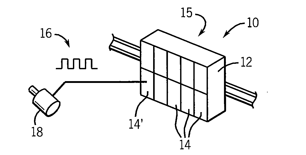
[0025]Referring now to FIG. 1, an industrial control I / O unit 10 may provide for a housing 12 holding multiple modules 14 including those supporting terminal blocks, input and output circuits, power supplies, and network communication devices. Each of these modules 14 may communicate on a common backplane 15 distributing power to the modules 14 and providing a communication path for data between the modules 14 and between the I / O unit 10 and a remote industrial control system (not shown) via a network communication device.

[0026]A frequency monitoring module 14′ may receive an input signal 16, for example a square wave or other periodic signal from sensors on controlled equipment, for example a tachometer, 18 which provides signal 16 whose frequency changes in proportion to a rotational rate of the tachometer 18 when attached to a rotating machine or the like. Other signal sources include, for example, optical switches and the like.

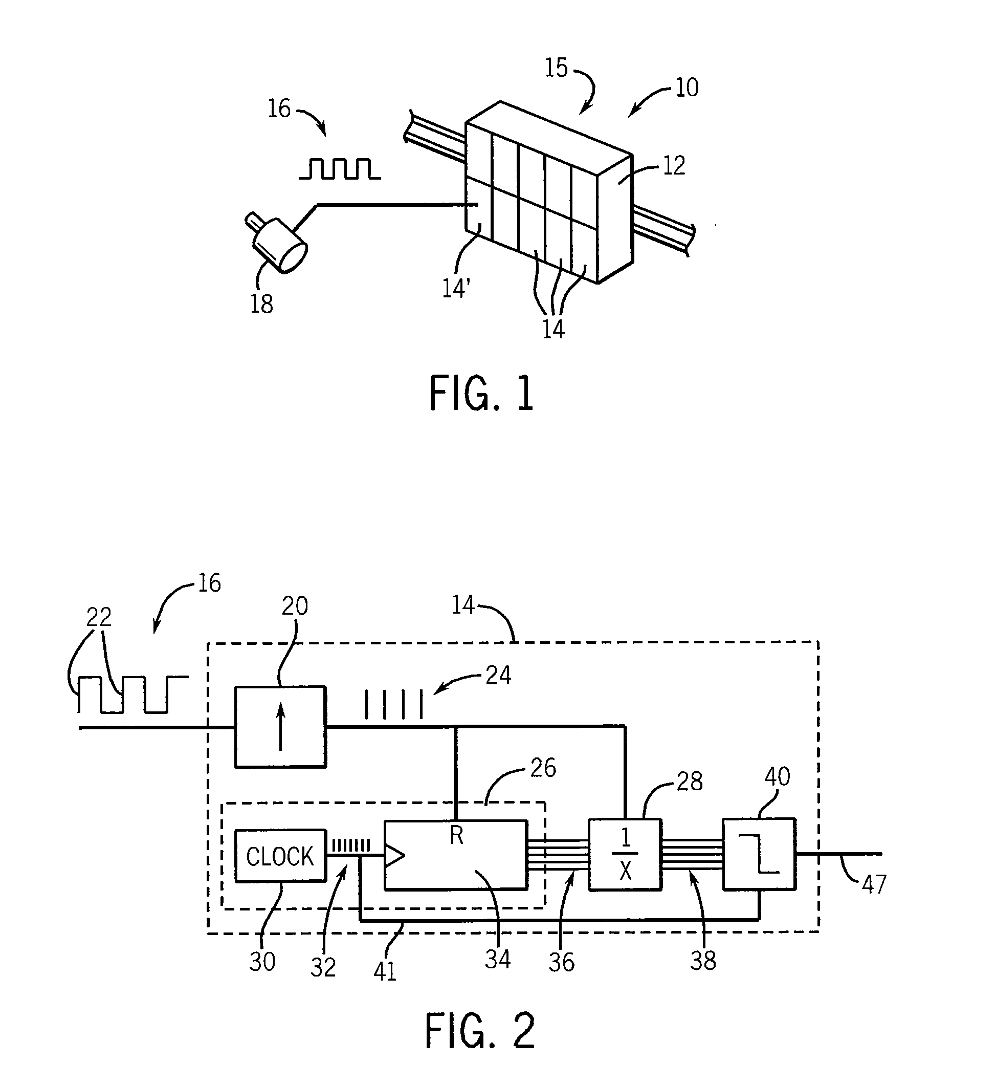
[0027]Referring now to FIG. 2, the input signal 16 m...


PUM


Abstract

A frequency monitor provides high resolution frequency monitoring over a range of input signal frequencies by measuring the time period of the signal to produce a raw frequency value and then filtering the raw frequency value with a low pass filter to remove an error component caused by quantization effects at high input signal frequencies. The system automatically accommodates changes in the input frequency eliminating a need for manual adjustment of the system based on anticipated measured frequencies.

Description

FIELD OF THE INVENTION[0001]This application generally relates to frequency monitors for measuring the frequency of a periodic signal and particularly to a frequency monitor that may automatically accommodate a wide range of input frequencies with high resolution.BACKGROUND[0002]Frequency monitors may be employed to measure periodic signals, for example, electrical pulses from a tachometer or the like. Low-frequency signals are typically measuring the time between signal “features” of two successive cycles of the signal, for example, the rising edge of a square-wave pulse or zero crossing of a sine wave. The measured time may be obtained by counting “ticks” of a high-speed clock between the occurrence of these signal features and this count may be inverted to obtain a measure of frequency.[0003]As the frequency rises, the number of measured clock ticks falls decreasing the effective resolution of the measurement. This decrease in resolution may be avoided by increasing the resolutio...

Claims


Application Information

Patent Timeline
IPC IPC(8): G01R23/02
CPCG01R23/10
Inventor HOPSECGER, EDWARDGOODNETTER, DAVID R.
Owner ROCKWELL AUTOMATION TECH
Why Eureka
Try Eureka