Light diffusing film, polarizing plate with light diffusing film, liquid crystal display device, and lighting equipment

a technology of light diffusing film and polarizing plate, which is applied in the direction of polarizing elements, lighting and heating apparatus, instruments, etc., can solve the problems of reducing the efficiency of light utilization, reducing the light diffusing element obtained difficulty, and none of the technologies have provided light diffusing elements satisfying both. , to achieve the effect of strong light diffusibility, excellent production efficiency and suppressing backscatter

Active Publication Date: 2013-09-19
NITTO DENKO CORP
View PDF6 Cites 5 Cited by
  • Summary
  • Abstract
  • Description
  • Claims
  • Application Information

AI Technical Summary

Benefits of technology

[0022]According to the present invention, an extremely thin light diffusing film which has strong light diffusibility and in which backscattering is suppressed can be realized. Specifically, the following light diffusing film can be realized. The film has a light diffusion half-value angle of 30° or more, its light diffusion half-value angle and backscattering ratio have a specific relationship, and its thickness is 4 μm to 25 μm. Although a strongly diffu...

Problems solved by technology

Therefore, it is difficult for the conventional light diffusing element obtained by simply dispersing the fine particles in the matrix to realize high image quality or high lighting quality.
Further, the enlargement of the backscattering in the conventional light diffusing element is incomp...

Method used


Image

  • Light diffusing film, polarizing plate with light diffusing film, liquid crystal display device, and lighting equipment
  • Light diffusing film, polarizing plate with light diffusing film, liquid crystal display device, and lighting equipment
  • Light diffusing film, polarizing plate with light diffusing film, liquid crystal display device, and lighting equipment

Examples


example 1

Production of Light Diffusing Film

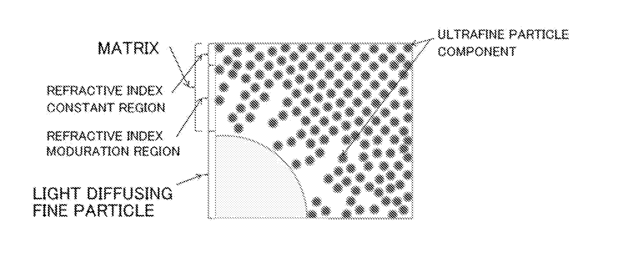
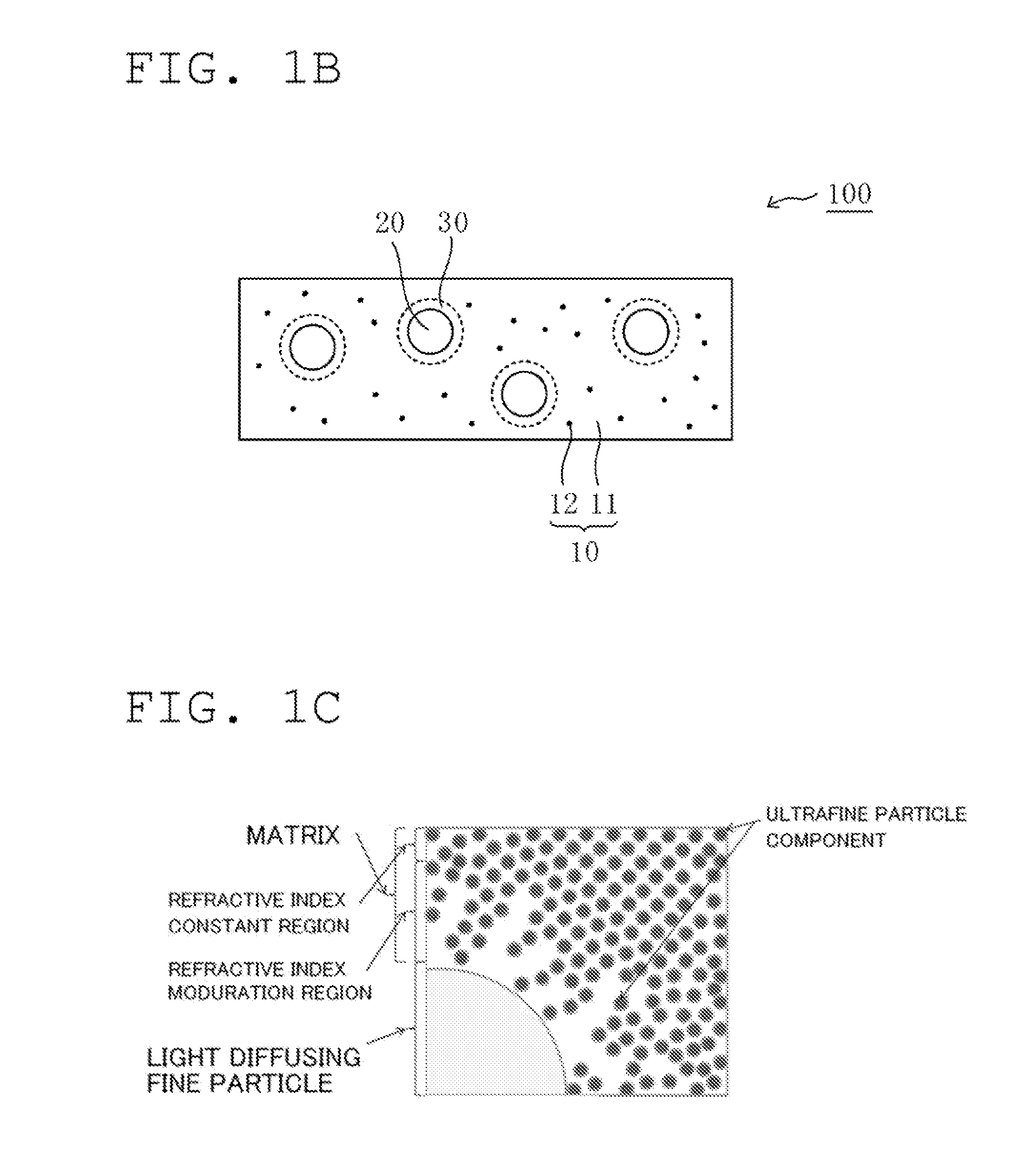
[0126]To 100 parts of a hard coat resin (“Opstar KZ6661” (trade name) (containing MEK / MIBK), manufactured by JSR Corporation) containing 62% of zirconia nano particles (average primary particle diameter: 10 nm, average particle diameter: 60 nm, refractive index: 2.19) as an ultrafine particle component, 11 parts of a 50% methyl ethyl ketone (MEK) solution of pentaerythritol triacrylate (“Biscoat #300” (trade name), refractive index: 1.52, manufactured by Osaka Organic Chemical Industry Ltd.) as a precursor of a resin component, 0.5 part of a photopolymerization initiator (“Irgacure 907” (trade name), manufactured by BASF Japan Ltd.), 0.5 part of a leveling agent (“RS721” (trade name), manufactured by DIC Corporation), and 15 parts of polymethyl methacrylate (PMMA) fine particles (“XX-131AA” (trade name), average particle diameter: 2.5 μm, refractive index: 1.49, manufactured by Sekisui Plastics Co., Ltd.) as light diffusing fine particles were added...

example 2

Production of Light Diffusing Film

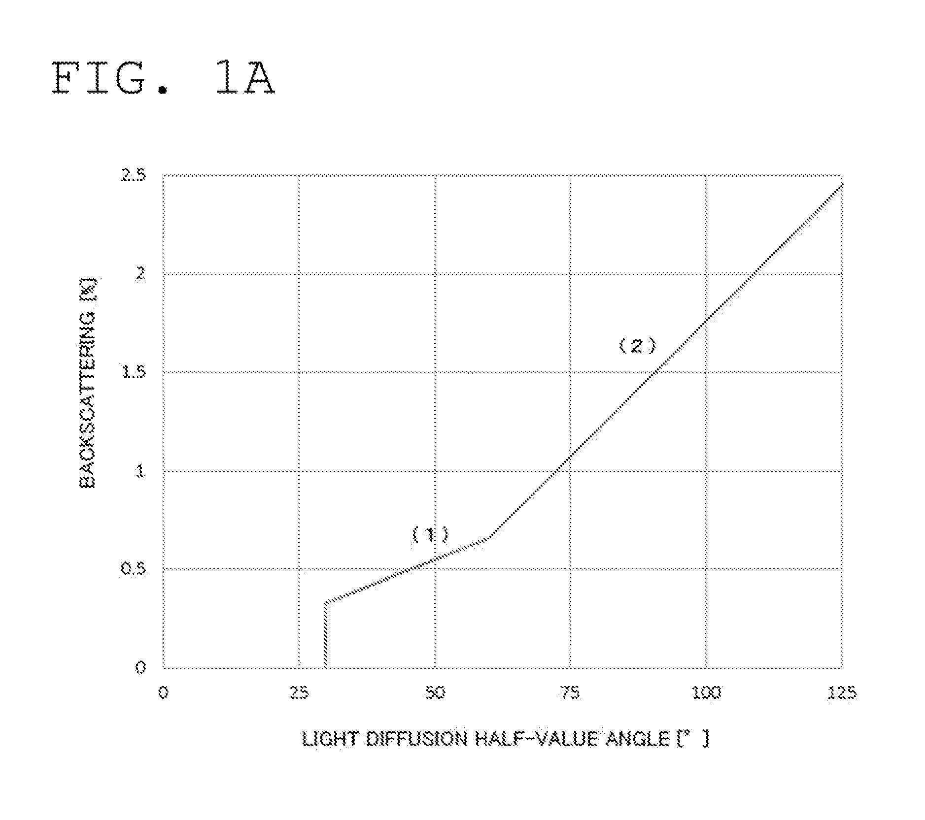
[0127]A light diffusing film having a thickness of 10.2 μm was obtained in the same manner as in Example 1 except that the application thickness of the application liquid was changed. The obtained light diffusing film was subjected to the evaluations (1) to (6). Table 1 shows the results. A relationship between a light diffusion half-value angle and a backscattering ratio satisfied the expressions (1) and (2).

example 3

Production of Light Diffusing Film

[0128]A light diffusing film having a thickness of 14.3 μm was obtained in the same manner as in Example 1 except that the application thickness of the application liquid was changed. The obtained light diffusing film was subjected to the evaluations (1) to (6). Table 1 shows the results. A relationship between a light diffusion half-value angle and a backscattering ratio satisfied the expressions (1) and (2).


PUM


Abstract

There is provided an extremely thin light diffusing film, which has strong light diffusibility, has suppressed backscattering, and is excellent in productivity. The light diffusing film includes: a first region having a first refractive index; a substantially spherical shell-shaped refractive index modulation region surrounding the first region; and a second region having a second refractive index, the region being positioned on a side of the refractive index modulation region opposite to the first region. The light diffusing film has a light diffusion half-value angle of 30° or more and a thickness of 4 μm to 25 μm, and satisfies the following expressions (1) and (2):
y≦0.011x (30≦x≦60)  (1)
y≦0.0275x−0.99 (60<x)  (2)
where x represents the light diffusion half-value angle (°) and y represents a backscattering ratio (%), the expressions (1) and (2) each representing a relationship between a numerical value for the light diffusion half-value angle and a numerical value for the backscattering ratio.

Description

TECHNICAL FIELD[0001]The present invention relates to a light diffusing film, a polarizing plate with a light diffusing film, a liquid crystal display device, and a lighting equipment.BACKGROUND ART[0002]A light diffusing element is typically a sheet-shaped optical element including a resin matrix and fine particles dispersed in the matrix, and expresses light diffusibility on the basis of a difference in refractive index between each of the fine particles and the matrix (see, for example, Patent Literature 1). The light diffusing element has been widely utilized in, for example, a lighting cover, a screen for a projection television, or a surface-emitting device (e.g., a liquid crystal display device). In any one of the applications of the light diffusing element, such characteristics as the realisation of high image quality or high lighting quality, an improvement in efficiency for light utilization, and industrially excellent production efficiency have been required. The light di...

Claims


Application Information

Patent Timeline
IPC IPC(8): G02B5/02G02F1/1335
CPCG02B5/0242G02F1/133504G02B5/0278G02B5/02G02B5/30G02F1/1335
Inventor NISHIMURA, AKINORINAKAMURA, KOZOTAKEMOTO, HIROYUKIFUCHIDA, TAKEHITO
Owner NITTO DENKO CORP
Why Eureka
Try Eureka