

Light reflector and planar light source device
a light reflector and planar light source technology, applied in the field of light reflectors, can solve the problems of increasing the demand for further brightness, discoloration, yellowing of light reflectors, etc., and achieves excellent light diffusibility, high brightness, and high reflectivity.
- Summary
- Abstract
- Description
- Claims
- Application Information
AI Technical Summary
Benefits of technology
Problems solved by technology
Method used
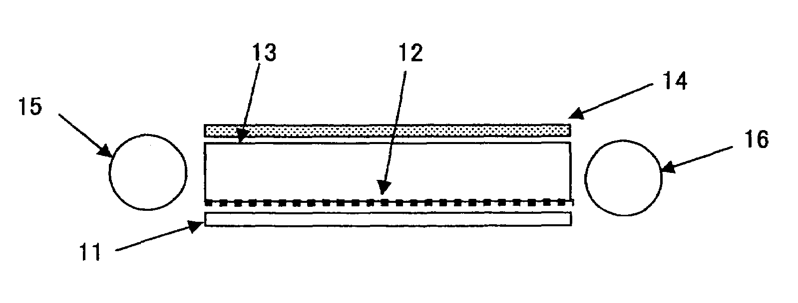
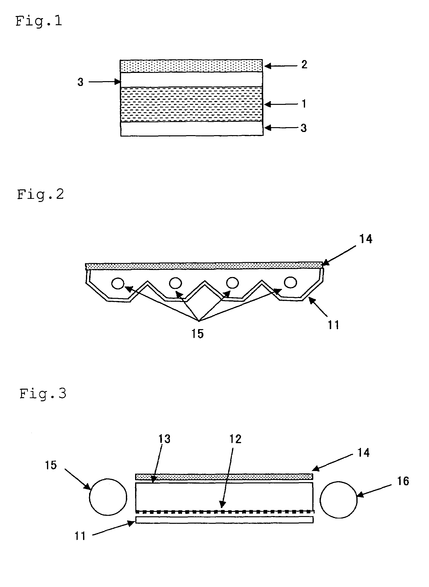
Image

Examples
example 1
[0060]A composition (A), a composition (B) and a composition (C) prepared by mixing the ingredients shown in Table 1 in the ratio shown in Table 2 were separately melt-kneaded in different extruders at 250° C. Next, these were fed to one co-extrusion die, in which (B) was laminated on the surface of (A) and (C) was on the back of (A), and sheetwise extruded out and cooled to about 60° C. with a chill roll to obtain a laminate of B / A / C.
[0061]The laminate was re-heated at 145° C., then stretched in the machine direction thereof by utilizing the peripheral speed difference between a number of rolls, again re-heated up to about 150° C., and stretched in the cross direction thereof in a tenter. Then, the laminate was re-heated at 160° C. and stretched in the cross direction thereof in a tenter. Next, this was annealed at 160° C. and then cooled to 60° C., and its edges were trimmed away to give a three-layered laminate film. The laminate film is used as a light reflector.
example 2
[0062]A composition (A) prepared by mixing the ingredients shown in Table 1 in the ratio shown in Table 2 was melt-kneaded in an extruder at 250° C. Then, this was sheetwise extruded out, and cooled to about 60° C. with a chill roll to obtain a substrate layer (A). The substrate layer (A) was re-heated at 145° C., and then stretched in the machine direction to the draw ratio as in Table 2, by utilizing the peripheral speed difference between a number of rolls.
[0063]Compositions (B) and (C) prepared by mixing the ingredients shown in Table 1 in the ratio shown in Table 2 were melt-kneaded, and extruded out onto both faces of the substrate layer (A) to form a light-diffusive layer (B) and an interlayer (C) thereon, thereby giving a laminate of B / C / A / C. Then, the laminate was re-heated at 160° C. and stretched in the cross direction to the draw ratio as in Table 2, in a tenter. Next, this was annealed at 160° C. and then cooled to 60° C., and its edges were trimmed away to give a four-...
example 3
[0064]A light reflector was obtained in the same manner as in Example 2, for which, however, the ingredients in Table 1 were mixed in the ratio as in Table 2.
PUM
| Property | Measurement | Unit |
|---|---|---|
| reflectance R2 | aaaaa | aaaaa |
| reflectance R2 | aaaaa | aaaaa |
| surface roughness index | aaaaa | aaaaa |
Abstract
Description
Claims
Application Information