Exposure apparatus

Inactive Publication Date: 2013-09-19
V TECH CO LTD
View PDF3 Cites 2 Cited by
  • Summary
  • Abstract
  • Description
  • Claims
  • Application Information

AI Technical Summary

Benefits of technology

[0014]According to a first aspect of the present invention, it is possible to expand the exposure area simply by arranging a plurality of pattern generators and a plurality of microlens substrates having fixed sizes. In this case, even when the plurality of pattern generators are arranged, there is no need to increase the size of the lens in a manner different from conventional techniques, and accordingly, it is possible to easily expand the exposure area without having the problem of lens aberration. Furthermore, since it is only necessary to prepare pattern generators and microlens substrates that are standardized and have fixed sizes, it is possible to reduce increases in production costs of elements,
[0015]Furthermore, according to a second aspect of the present invention, it is possible to form a film for separating source light into two linearly polarized light components of P waves and S waves, respectively, and

Problems solved by technology

Considering production costs of such a micromirror device, aberration of the le

Method used


Image

  • Exposure apparatus
  • Exposure apparatus
  • Exposure apparatus

Examples


Embodiment Construction

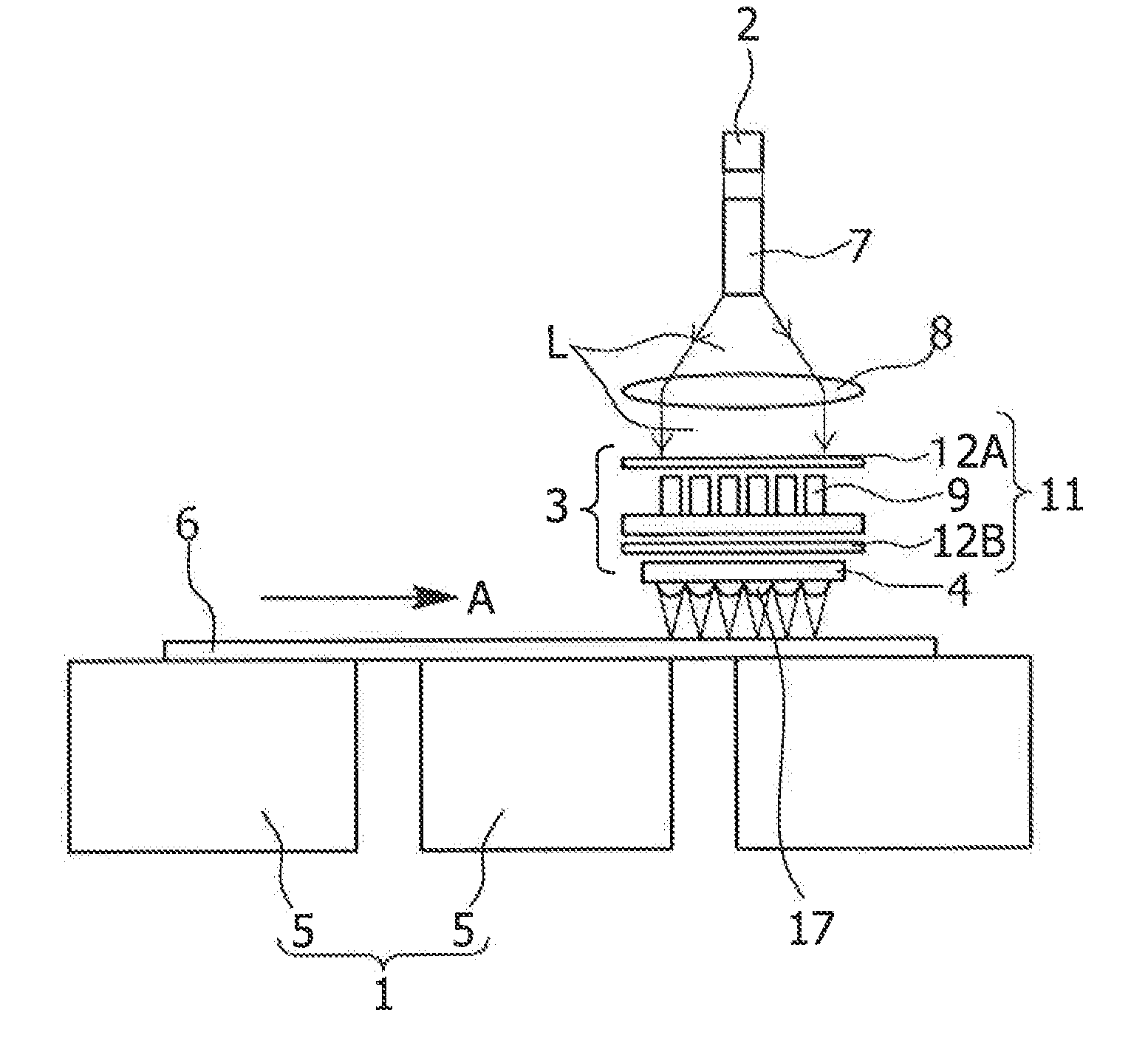
[0025]Hereinbelow, embodiments of the present invention will be described in detail with reference to attached drawings. FIG. 1 is a front view illustrating an embodiment of an exposure apparatus of the present invention. This exposure apparatus is configured to optically modulate source light by using a pattern generator to generate an exposure pattern of bright and dark form and to carry out exposure. The apparatus includes a stage system 1, a light source 2, a pattern generator 3 and a microlens substrate 4.

[0026]The stage system 1 is configured to scan an object to be exposed 6, which is placed on an upper surface of a stage 5, in the direction indicated by an arrow A at a constant speed. For example, while the object to be exposed 6 is lifted a constant amount off an upper surface of a stage 5 by air blown and drawn by the stage 5, both edges of the object to be exposed 6 in the direction indicated by an arrow A are held by a moving mechanism, not shown, and the object to be ex...


PUM


Abstract

An exposure apparatus includes a pattern generator with light switches arrayed on a plane parallel to a surface of an object to be exposed. Each of the light switches has a switching element that is a rectangular pillar of an electro-optic crystal, and a pair of polarizers arranged on respective sides in the long axis direction of the switching element. The exposure apparatus drives the light switches individually to generate an exposure pattern having a certain bright and dark form and irradiate the object to be exposed with the pattern. Furthermore, the exposure apparatus has a plurality of microlenses provided on the light-output side of the pattern generator so that the optical axes of the microlenses are aligned to the longitudinal center axes of the switching elements, so as to project images of light-output ends of the switching elements at reduced size onto the object to be exposed.

Description

[0001]This application is a continuation application of PCT / JP2011 / 073840, filed on Oct. 17, 2011.BACKGROUND OF THE INVENTION[0002]1. Field of the Invention[0003]The present invention relates to a maskless exposure apparatus which includes a pattern generator for optically modulating source light to produce exposure patterns of bright and dark and carries out exposure, and in particular, relates to an exposure apparatus capable of easily expanding an exposure area.[0004]2. Description of Related Art[0005]Conventionally, such an exposure apparatus employs a digital micromirror device as a pattern generator, which has a plurality of two-dimensionally arranged micromirrors, each capable of adjusting reflection angle, to optically modulate source light to generate exposure patterns of bright and dark, and irradiates an object to be exposed with such an exposure pattern via an objective lens (for example, refer to Japanese Patent Application Laid-open (Kokai) Publication No. 2010-141245)...

Claims


Application Information

Patent Timeline
IPC IPC(8): G03F7/20
CPCG03F7/70191G03F7/70291G03F7/70275G03F7/20
Inventor MIZUMURA, MICHINOBU
Owner V TECH CO LTD
Why Eureka
Try Eureka