System and Method for Optimized Automated Layout of Solar Panels

a solar panel and automated layout technology, applied in photovoltaic supports, sustainable buildings, instruments, etc., can solve the problems of low cost of solar panel production, crude cad tools, and high cost of grid power, and achieve convenient and accurate layout, the effect of facilitating the optimal layout of the ground

Inactive Publication Date: 2013-09-19
MODSOLAR
View PDF12 Cites 48 Cited by
  • Summary
  • Abstract
  • Description
  • Claims
  • Application Information

AI Technical Summary

Benefits of technology

[0014]Recognizing the need to provide a convenient yet accurate way to facilitate the optimal layout of ground- or roof-mounted solar panels, the present invention provides systems and methods for automated layout of solar panels within designated regions, optimized to achieve one or more specific goals of an installation, and offering a user the ability to designate options, parameter values and constraints that impact the underlying layout algorithm(s), as well as the ability to compare the panel layouts that are the result of the application of those algorithms.

Problems solved by technology

In the mid-1990s, the industry reached a point where the cost of producing solar panels (or modules, as they're sometimes called) was low enough that they could also be used in areas with grid connectivity, but where grid power was still very expensive.
Initially, these CAD tools were crude, but the time required to edit was about half what hand-drawn diagrams would require.
However, CAD still suffered from a host of limitations, most prominently relying on abstractions of physical objects, whether it be an area of land or a building, when deciding where to put the solar panels, as well as the inability to compare equipment for use in a particular project, thus leading to suboptimal equipment choices for a given area.
As the industry continued to scale, and as the cost of solar continued to drop in the late 1990s and early 2000s, the cost of producing full engineering diagrams via CAD was becoming prohibitive, and the industry began to search for other tools that could speed up the design process.
While a major step forward, such tools still had 3 major limitations: (1) users of these tools were still designing a system on an abstraction of an actual physical location or building on the earth; (2) these tools still relied upon the user to know and confirm that the spatial measurements they were using were correct; and (3) the user was unable to compare different solar modules to determine which would be the optimal choice for a given space.
Although they improved the efficiency of the design process, these tools were never intended to address the financial aspects of constructing a solar PV system.
The major limitation with these new tools was their reliance on the user to know the system design before quoting could occur.
Although this approach broke the “abstraction” problem by allowing the user to specify and measure areas on satellite imagery, the calculations were far too approximate—and therefore inaccurate—to be practical.
But such tools lack the integrated calculation of energy production—an essential piece of input to the cost / benefit analysis.
And none of these tools offers a convenient way to compare different layouts produced using different manufacturers' panels or different goals for the array (such as maximizing energy production).
Consequently, the industry continues to suffer in that the tools available form an artificial barrier between system design and financial estimation with sufficient accuracy.
While many of the abstracted design tools do a good job of representing a solar panel layout that a user desires, they lack the real-world interface.
Besides the integration problem existing in the industry, no design tool in the industry streamlined the process of designing a solar system by providing an automated and accurate means of laying out solar modules in a given space.

Method used


Image

  • System and Method for Optimized Automated Layout of Solar Panels
  • System and Method for Optimized Automated Layout of Solar Panels
  • System and Method for Optimized Automated Layout of Solar Panels

Examples


Embodiment Construction

[0048]Illustrative and alternative embodiments of the invention will be discussed in detail, as follows, with reference to FIGS. 1-33 provided with this application. The embodiments are provided to illustrate aspects of the invention, but the invention is not limited by any embodiment. The scope of the invention encompasses numerous alternatives, modifications, and equivalents.

[0049]Numerous specific details are set forth in the following description in order to provide a thorough understanding of the invention. However, the invention may be practiced according to the claims without some or all of these specific details. For the purpose of clarity, technical material that is known in the technical fields related to the invention has not been described in detail so that the invention is not unnecessarily obscured.

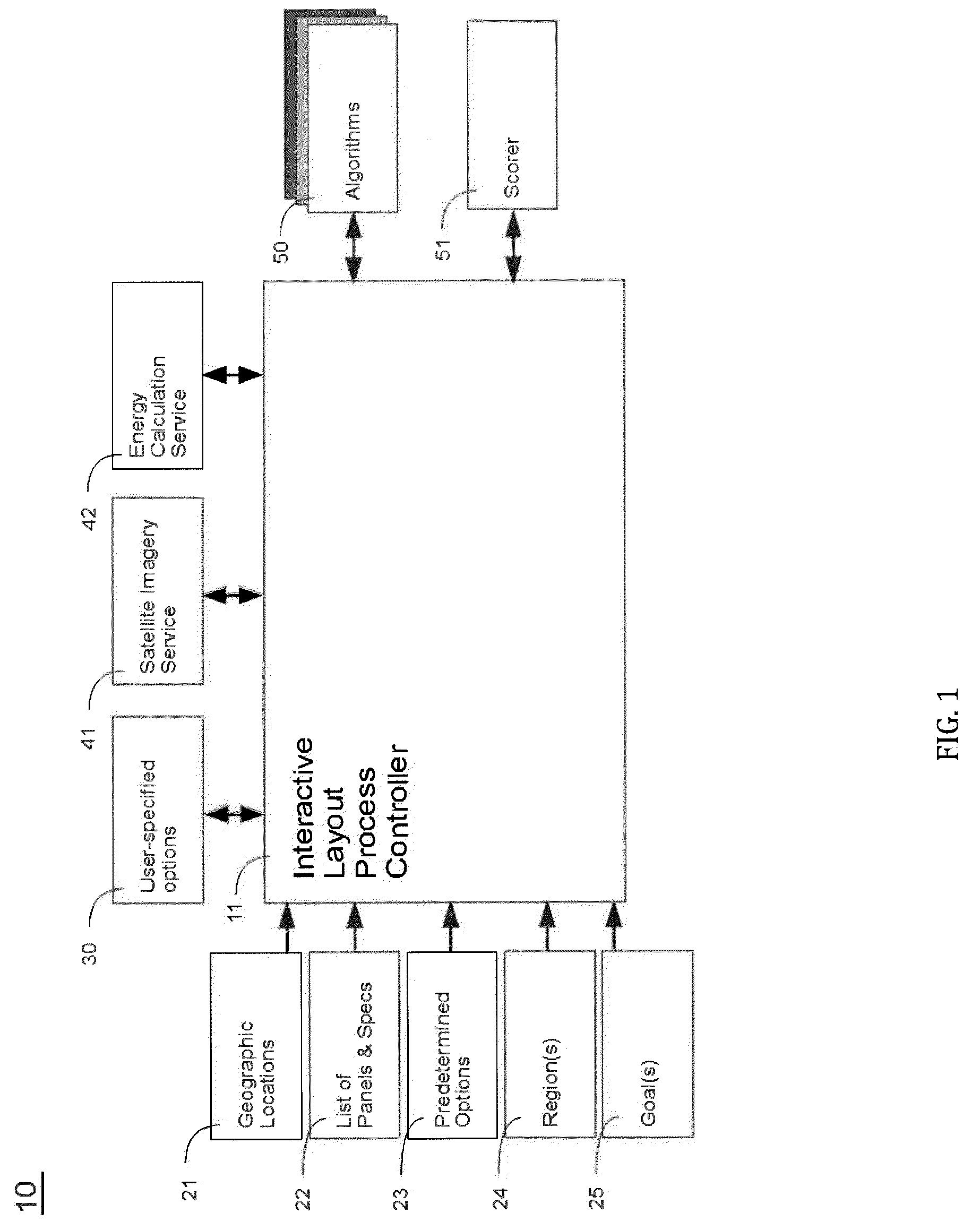
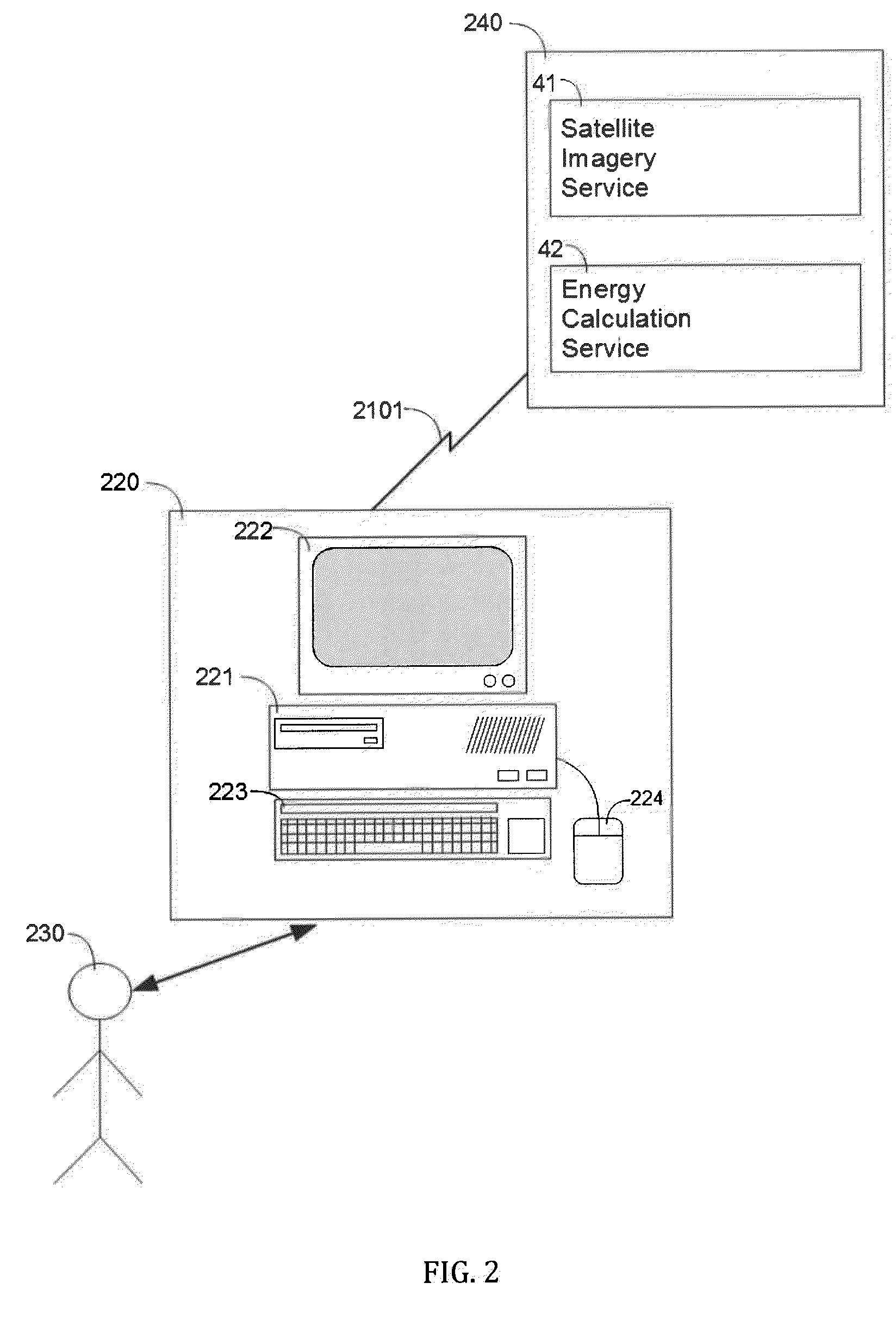
[0050]The description first discusses the hardware and software context in which the invention can be embodied. This is followed by an overview of the major components of th...


PUM


Abstract

The present invention provides an automated system and method for laying out photovoltaic (PV) solar panels on one or more regions of a roof or ground installation. Automation includes a presentation of optimal comparative layouts, use of different panels (of the same or different manufacturers), and consideration of different energy production characteristics and different layout constraints. Diverse mathematical approaches are used to determine the optimal panel layout for a given geographic region and for particular goals, including, but not limited to, the objective of maximizing the solar production from the designated region(s). The application of two such mathematical algorithms are detailed as parts of an exemplary embodiment: a deterministic edge-aligned approach as well as a nondeterministic approach that employs a genetic evolution simulation.

Description

CROSS REFERENCE TO RELATED APPLICATION[0001]This utility application claims the priority and benefit of U.S. Provisional Patent Application Ser. No. 61 / 533,356, entitled “System and Method for Optimized Automated Layout of Solar Panels,” filed Sep. 12, 2011, the entirety of which is incorporated herein by reference.FIELD OF INVENTION[0002]The present invention relates to methods, systems, and encoded computer readable mediums including electrical computers and data processing systems applied to automating the layout of individual solar photovoltaic (“PV”) panels on a roof or ground property in order to form a solar energy collection and electrical production system. In particular, the invention is concerned with optimizing the layout according to a desired individual or compound goal, and presenting optimal layouts for different manufacturers' panels and different layout options, in a format that facilitates easy comparison and final selection of a particular derived layout for a pa...

Claims


Application Information

Patent Timeline
Patent Type & Authority Applications(United States)
IPC IPC(8): G06F17/50
CPCH01L31/042G06F17/50G06F17/5004Y02B10/12Y02E10/50G06F30/13Y02B10/10H02S50/00H02S20/24G06F30/00
Inventor DERSHOWITZ, MICHAELILSEN, KEVINZAUHAR, RANDY J.
Owner MODSOLAR
Why Eureka
Try Eureka