
Method and magnetic resonance system to acquire mr data in a predetermined volume segment of an examination subject

a magnetic resonance and volume segment technology, applied in the field of methods and magnetic resonance systems, can solve the problems of reduced diagnostic quality, risk, chemically shifted spin species not being excited in the examination volume, etc., and achieve the effect of avoiding impairing the signal

Active Publication Date: 2013-09-26
SIEMENS HEATHCARE GMBH
View PDF5 Cites 15 Cited by
  • Summary
  • Abstract
  • Description
  • Claims
  • Application Information

AI Technical Summary

Benefits of technology

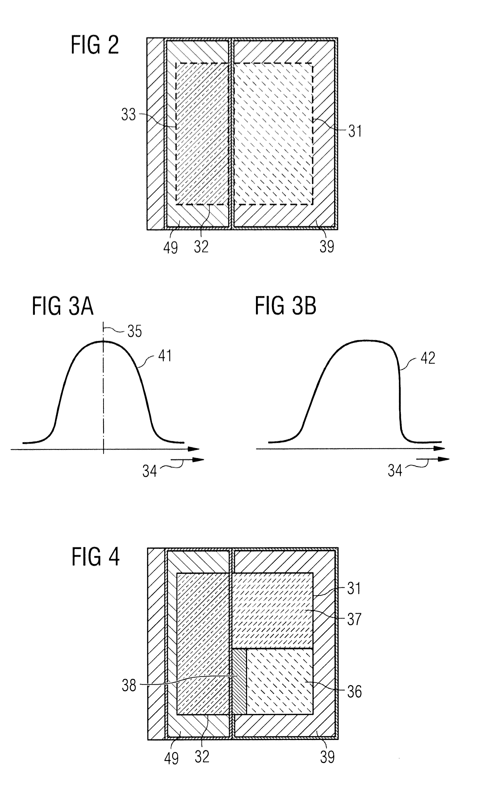
The present invention aims to reduce the risk of impairing signals in a volume segment being examined and ensure optimal incorporation of the entire volume segment into the imaging process. It does this by adjusting the center frequency of the magnetic field and the direction of the magnetic field gradient, which reduces the risk of chemically shifted spin species affecting the signal. Additionally, the invention ensures that the actual saturation volume segment is shifted away from the predetermined volume segment, reducing the risk of incorrect saturation in regions of the predetermined volume segment.

Problems solved by technology

For example, a movement (due to a respiration of the examination subject, for example), a flow or a pulsation (in blood vessels, for example) can lead to artifacts that are not only locally limited to the corresponding region but also are visible in the entire MR image, and thus can lead to a reduced diagnostic quality.
In the excitation case (the first possibility), the risk exists that chemically shifted spin species may not be excited in the examination volume.
Both situations lead to a reduced diagnostic quality of the MR images since relevant information is not acquired from the volume segment to be examined, and therefore is missing in the created MR images.

Method used


Image

  • Method and magnetic resonance system to acquire mr data in a predetermined volume segment of an examination subject
  • Method and magnetic resonance system to acquire mr data in a predetermined volume segment of an examination subject
  • Method and magnetic resonance system to acquire mr data in a predetermined volume segment of an examination subject

Examples


Embodiment Construction

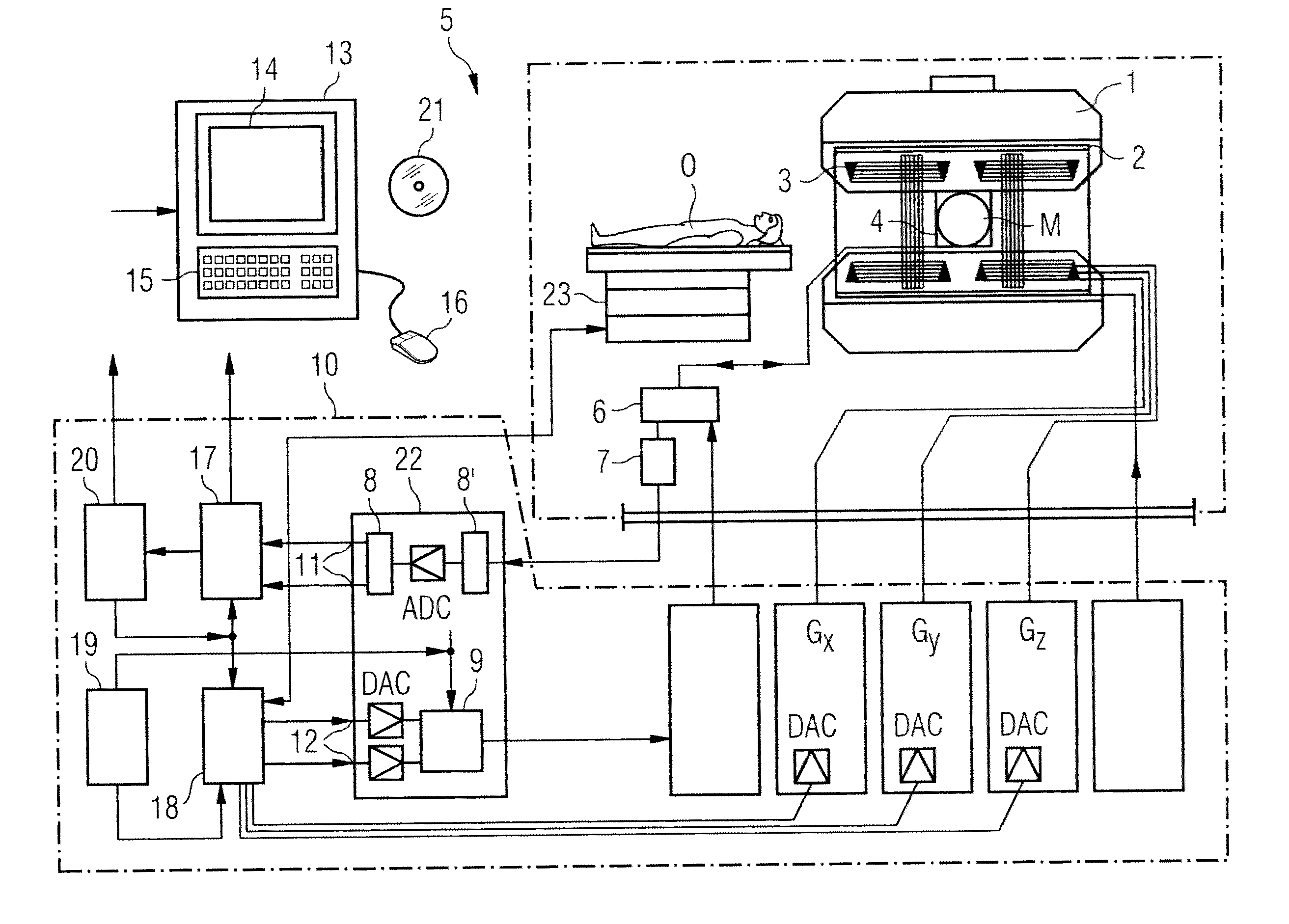
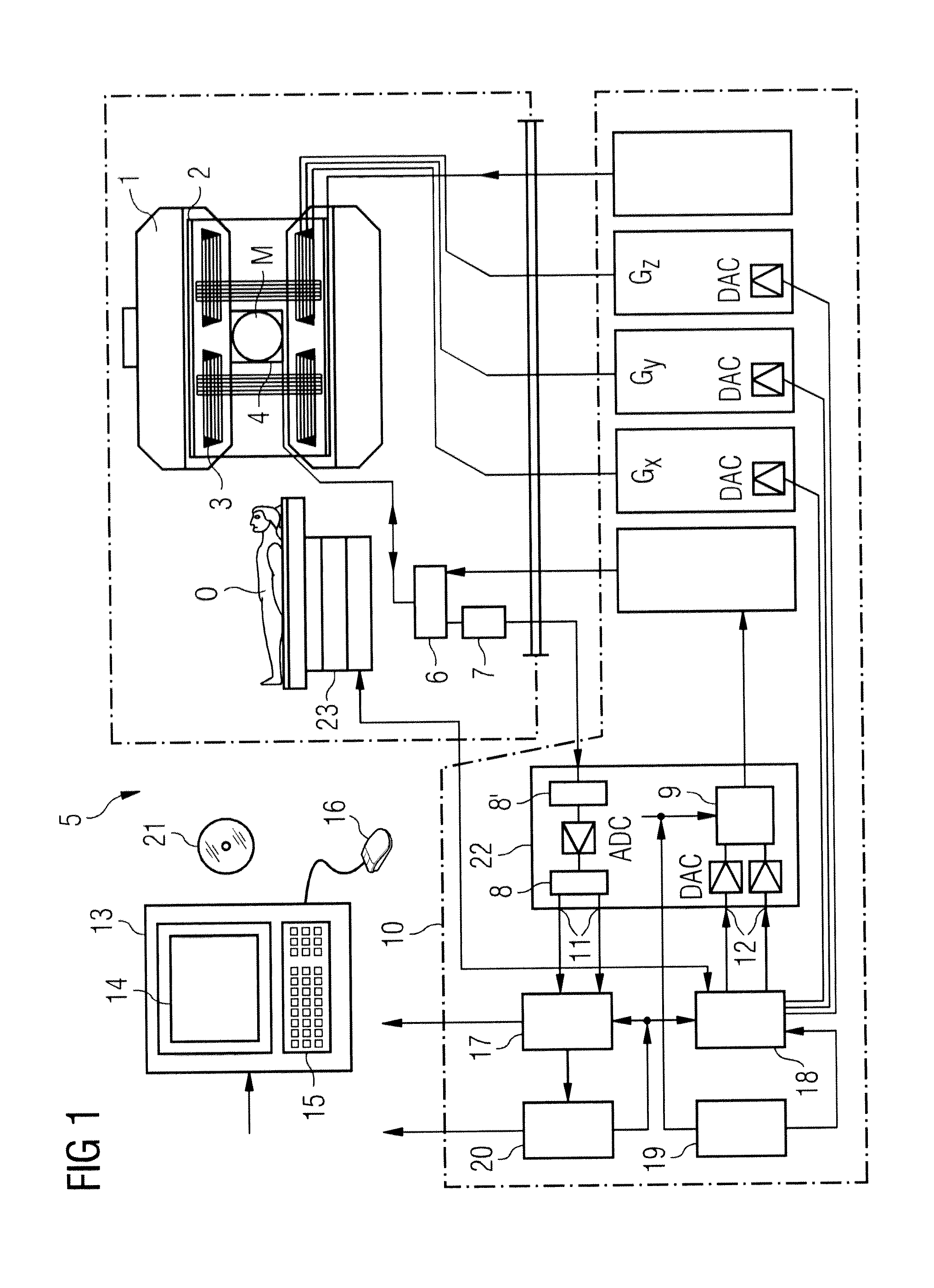
[0091]FIG. 1 shows a schematic presentation of a magnetic resonance system 5 (of a magnetic resonance imaging or nuclear magnetic resonance tomography apparatus). A basic field magnet 1 generates a temporally constant, strong magnetic field for polarization or alignment of the nuclear spins in a volume segment of a subject O (for example of a part of a human body that is to be examined). The subject O, lying on a table 23, is driven into the magnetic resonance system 5 for examination or measurement (data acquisition). The high homogeneity of the basic magnetic field that is required for the magnetic resonance measurement is defined in a typically spherical measurement volume M in which the parts of the human body that are to be examined are located. Shim plates made of ferromagnetic material are mounted at a suitable location to support the homogeneity requirements, and in particular to eliminate temporally invariable influences.

[0092]A cylindrical gradient coil system 3 having thr...


PUM


Abstract

In a method and a magnetic resonance (MR) system, a marked area is determined that demarcates a predetermined volume segment of the subject relative to the regions adjacent thereto. Nuclei in the predetermined volume segment are excited, or nuclei in a region adjacent thereto are saturated with an RF excitation pulse at the same time a magnetic field gradient is activated. The center frequency of a frequency range of the RF excitation pulse and the direction of the magnetic field gradient are adjusted dependent on resonant frequencies of substances present within the predetermined volume segment in order, starting from the predetermined volume segment to shift an actual excitation volume segment excited by the RF excitation pulse toward the marked area, or to shift a saturation volume saturated by the RF excitation pulse away from the marked area. MR data are then acquired from the predetermined volume segment.

Description

BACKGROUND OF THE INVENTION[0001]1. Field of the Invention[0002]The present invention concerns a method and a magnetic resonance (MR) system to acquire MR data in a predetermined volume segment of an examination subject with the magnetic resonance system.[0003]2. Description of the Prior Art[0004]In both MR imaging and MR spectroscopy, it is often necessary to suppress unwanted signal contributions originating from a defined region, defined regions of the examination subject by suitable measures, or to specifically acquire only signal contributions originating from defined regions of the examination subject. For example, a movement (due to a respiration of the examination subject, for example), a flow or a pulsation (in blood vessels, for example) can lead to artifacts that are not only locally limited to the corresponding region but also are visible in the entire MR image, and thus can lead to a reduced diagnostic quality.[0005]A first possibility to restrict these artifacts, and t...

Claims


Application Information

Patent Timeline
IPC IPC(8): G01R33/563
CPCG01R33/563G01R33/56527G01R33/4838G01R33/4833
Inventor FEIWEIER, THORSTENKRELLMANN, CHRISTOFKUEHN, BERNDPAUL, DOMINIKPFEUFFER, JOSEFPREUSCHE, ELISABETHWOHLFARTH, KATRIN
Owner SIEMENS HEATHCARE GMBH
Learn More