Backlight Module

a backlight module and light guide technology, applied in the direction of lighting and heating apparatus, planar/plate-like light guides, instruments, etc., can solve the problems of increasing lcd thinning and increasing size, increasing the thickness of light guide boards, and increasing the thickness of lcd, so as to ensure the uniformity of irradiation, reduce manufacturing costs, and simplify the manufacturing process

Active Publication Date: 2013-09-26
SHENZHEN CHINA STAR OPTOELECTRONICS TECH CO LTD
View PDF1 Cites 16 Cited by
  • Summary
  • Abstract
  • Description
  • Claims
  • Application Information

AI Technical Summary

Benefits of technology

[0006]An objective of the present invention is to provide a backlight module, which comprises elastic bodies arranged between side plates of a backplane and a light guide board to securely retain the light guide board in the backplane so as to avoid special processing applied to the light guide board that is conventional taken for fixing the light guide board, simplify the manufacture process, reduce the manufacture cost, and also ensure the uniformity of irradiation and luminance of the entire backlight module and to provide a buffering space to the light guide board to avoid deformation of the light guide board caused by compression thereby improve the overall quality of the backlight module.

Problems solved by technology

However, the current trend of LCD is thinning and increasing size.
This makes the light guide board increasingly thin and the thermal expansion characteristics of the light guide board due to absorption of heat are getting prominent.
The movement of the light guide board may easily lead to problems, such as abrasion of the light guide board.
Further, since the light guide board comprises slot or projection structures, the manufacture cost is increased and the mechanical strength of the light guide board is reduced, so that breaking may occur on the light guide board when subjected to impacts caused by external forces.
Further, since the light guide board is provided in a circumference thereof with slot or projection, the optic path of light might get locally varied at the sides of the light guide board and this may cause certain optic problems, such as non-uniform brightness at edges of the backlight module, making the yield rate of slim bezel backlight module significantly reduced.

Method used


Image

  • Backlight Module
  • Backlight Module
  • Backlight Module

Examples


Embodiment Construction

[0024]To further expound the technical solution adopted in the present invention and the advantages thereof, a detailed description is given to preferred embodiments of the present invention and the attached drawings.

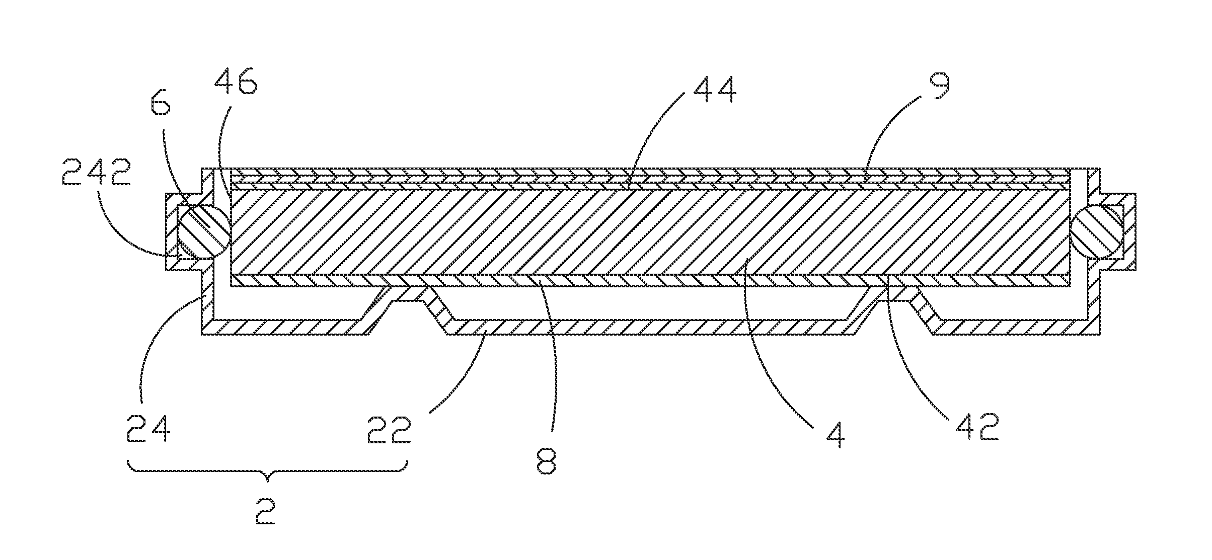
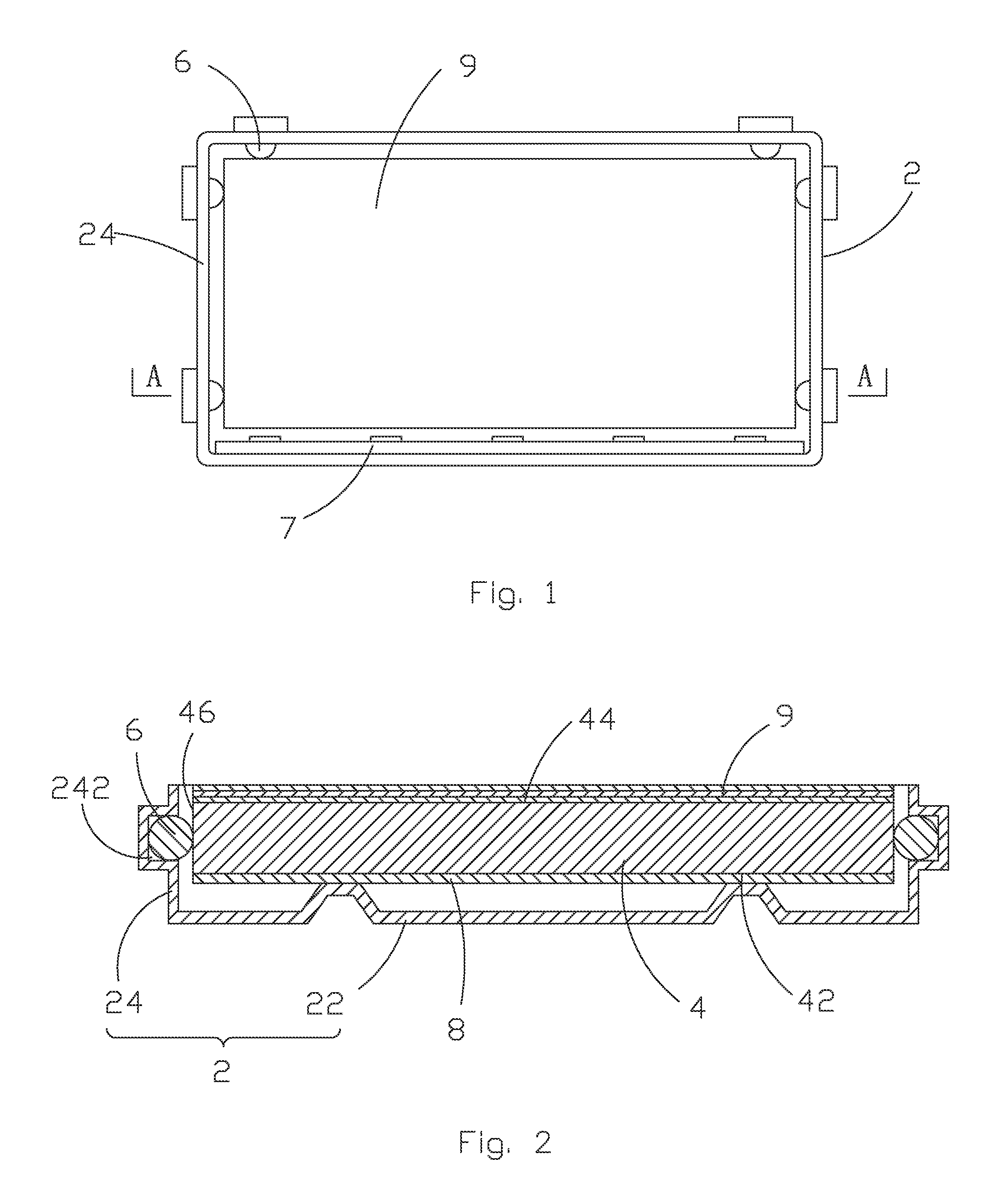
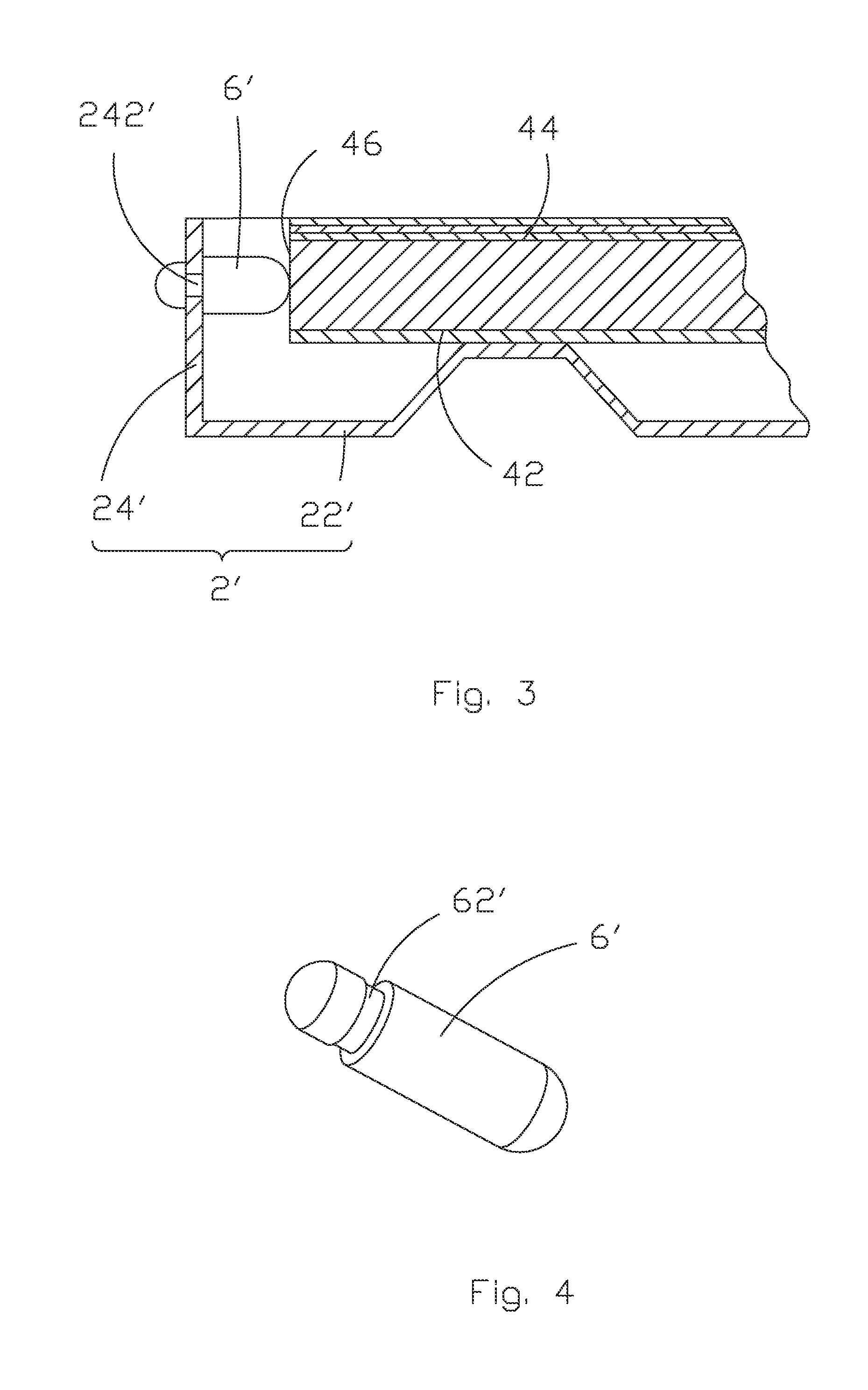
[0025]Referring to FIGS. 1 and 2, as an embodiment of backlight module according to the present invention, the backlight module comprises a backplane 2, a light guide board 4 arranged inside the backplane 2, and a plurality of elastic bodies 6 arranged between the backplane 2 and the light guide board 4. The backplane 2 comprises a bottom plate 22 and a plurality of side plates 24 perpendicularly mounted to a perimeter of the bottom plate 22. The light guide board 4 comprises a bottom surface 42 facing the bottom plate, a top surface 44 distant from the bottom plate, and a plurality of side surfaces 46 connecting between the bottom surface 42 and the top surface 44. The plurality of side surfaces 46 respectively opposes the plurality of side plates 24 of the backplane 2...


PUM


Abstract

The present invention provides a backlight module, which includes a backplane, a light guide board arranged inside the backplane, and a plurality of elastic bodies arranged between the backplane and the light guide board. The backplane includes a bottom plate and a plurality of side plates perpendicularly mounted to a perimeter of the bottom plate. The light guide board includes a bottom surface facing the bottom plate, a top surface distant from the bottom plate, and a plurality of side surfaces connecting between the bottom surface and the top surface. The elastic bodies are respectively mounted to three of the side plates of the backplane and are set abutting against three of the side surfaces of the light guide board. The elastic bodies form contact surfaces that engage the side surfaces of the light guide board and are curved surfaces or spherical surfaces.

Description

BACKGROUND OF THE INVENTION[0001]1. Field of the Invention[0002]The present invention relates to a backlight module, and in particular to a backlight module that comprises elastic bodies to retain a light guide board.[0003]2. The Related Arts[0004]Liquid crystal display (LCD) has a variety of advantages, such as compact device size, low power consumption, and being free of radiation, and is thus widely used. Most of the LCDs that are currently available in the market are backlighting LCDs, which comprise a liquid crystal display panel and a backlight module. The working principle of the liquid crystal display panel is that liquid crystal molecules interposed between two parallel glass plates and a plurality of vertical and horizontal fine electrical wires is arranged between the two glass plates, whereby the liquid crystal molecules are controlled to change direction by application of electricity to refract light emitting from the backlight module for generating images. Since the li...

Claims


Application Information

Patent Timeline
Patent Type & Authority Applications(United States)
IPC IPC(8): F21V17/02F21V13/12F21V8/00
CPCF21V13/12F21V13/14F21V17/164G02F1/133615G02B6/0093G02F2201/46G02F2201/50G02F2201/54G02B6/0088
Inventor CHEN, SHIHHSIANGQUE, CHENGWEN
Owner SHENZHEN CHINA STAR OPTOELECTRONICS TECH CO LTD
Why Eureka
Try Eureka