Thermally-assisted magnetic recording head, head gimbals assembly, head arm assembly, magnetic disk unit, and light transmission unit

a technology of magnetic recording head and magnetic disk, which is applied in the direction of recording information storage, mounting head within the housing, instruments, etc., can solve the problems of plasmon generator itself overheating and accordingly deformation, increasing the coercivity of magnetic disk, and increasing the difficulty of information recording using the existing magnetic head. , to achieve the effect of stably performing magnetic recording, increasing surface roughness and increasing density

Active Publication Date: 2013-09-26
SAE MAGNETICS (HK) LTD +1
View PDF2 Cites 8 Cited by
  • Summary
  • Abstract
  • Description
  • Claims
  • Application Information

AI Technical Summary

Benefits of technology

[0018]In the light transmission unit according to the embodiment of the invention, since the return light to the laser light source is allowed to be decreased, operation of the laser light source is stabilized. Therefore, when the light transmission unit is used in a thermally-assisted magnetic recording head, for example, variation in the intensity and the spot size of near-field light generated in an air bearing surface is suppressed, and thus magnetic recording with higher density is allowed to be stably performed.

Problems solved by technology

However, increasing the magnetic anisotropy energy of the magnetic microparticle leads to increase in the coercivity of the magnetic disk.
As a result, difficulty occurs in the information recording using the existing magnetic head.
In the method of directly applying light to a plasmon generator, however, the plasmon generator itself overheats and accordingly deforms, depending on usage environment or conditions.
Therefore, practical realization of the method is difficult.
However, when the light emission surface of the light source unit is close to the light incident surface of the waveguide, the intensity of the return light described above is increased so that stable operation of the laser diode may be obstructed.

Method used


Image

  • Thermally-assisted magnetic recording head, head gimbals assembly, head arm assembly, magnetic disk unit, and light transmission unit
  • Thermally-assisted magnetic recording head, head gimbals assembly, head arm assembly, magnetic disk unit, and light transmission unit
  • Thermally-assisted magnetic recording head, head gimbals assembly, head arm assembly, magnetic disk unit, and light transmission unit

Examples


first embodiment

[1. Configuration of Magnetic Disk Unit]

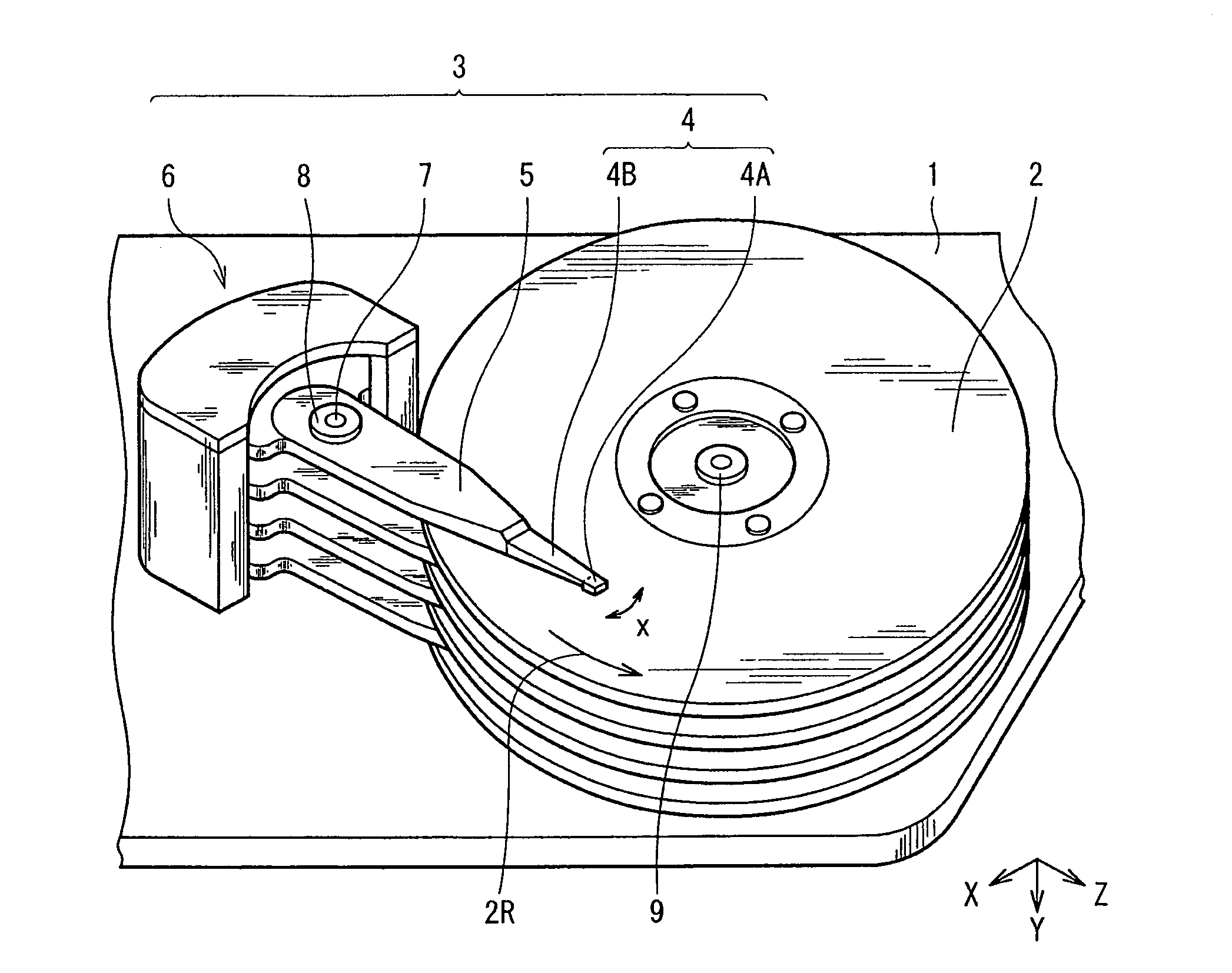
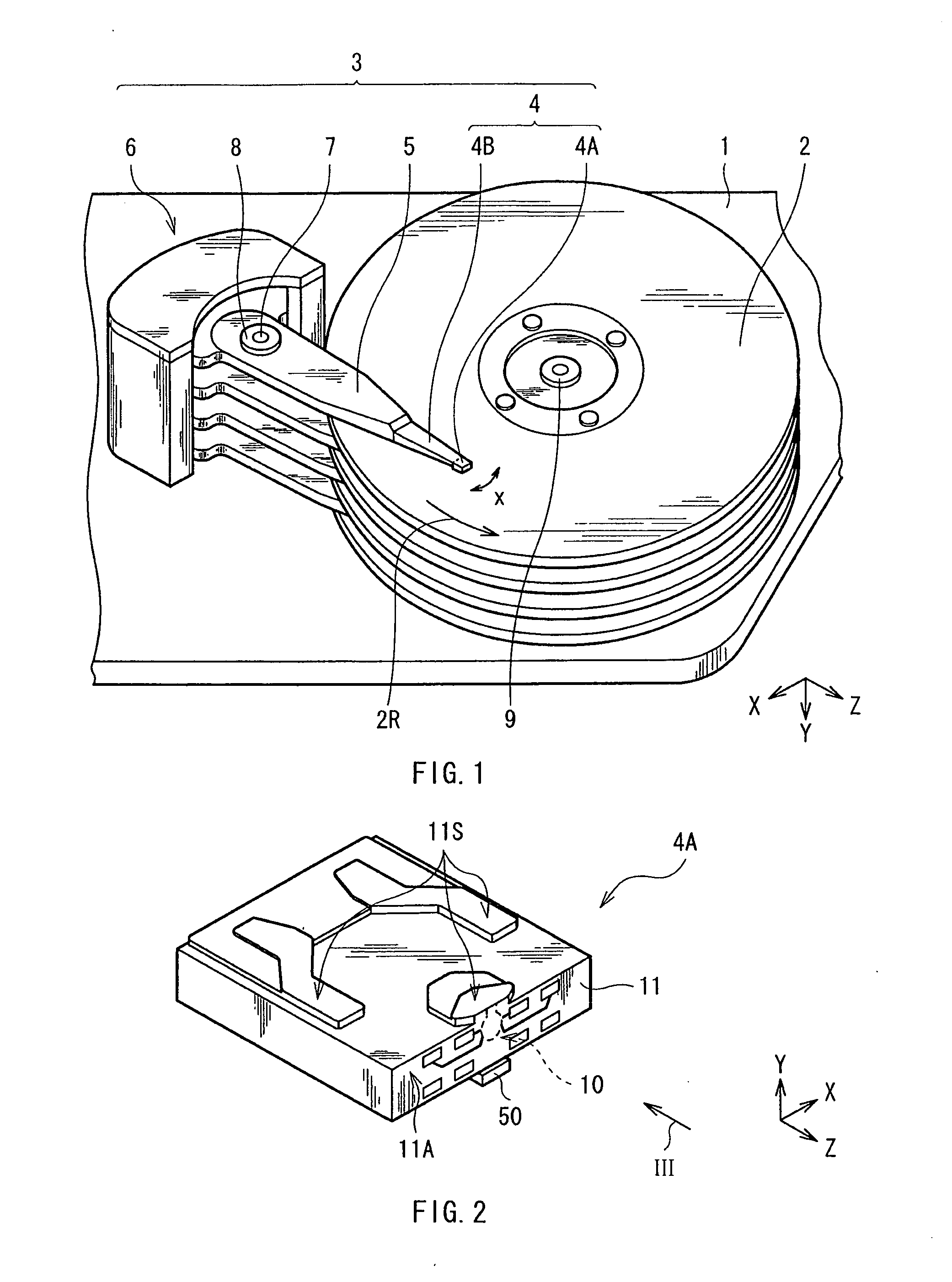
[0041]First, referring to FIG. 1 and FIG. 2, a configuration of a magnetic disk unit will be described below as a first embodiment of the invention.

[0042]FIG. 1 is a perspective view illustrating an internal configuration of the magnetic disk unit as the first embodiment. The magnetic disk unit adopts load / unload system as a driving system, and includes, for example, in a housing 1, a magnetic disk 2 as a magnetic recording medium in which information is to be written, and a head arm assembly (HAA) 3 for writing information in the magnetic disk 2 and reading the information. The HAA 3 is provided with a head gimbal assembly (HGA) 4, an arm 5 supporting a substrate of the HGA 4, and a driver 6 as a power source for rotating the arm 5. The HGA 4 includes a thermally-assisted magnetic head device (hereinafter, simply referred to as a “magnetic head device”) 4A having a side surface provided with a magnetic read write head section 10 (described la...

second embodiment

[0110]Next, a magnetic disk unit according to a second embodiment of the invention is described. In the second embodiment, the structure is similar to the above-described first embodiment except that a rear end surface of each of a core and a cladding in the magnetic write read head section 10 has a shape different from that of the core and the cladding in the first embodiment. Therefore, the shapes of the rear end surfaces will be described below, and the other description will be appropriately omitted.

[0111]FIGS. 18A and 18B each illustrate, in an enlarged manner, a shape of an opposed surface of the core and the cladding opposed to the laser diode 60 which is located on an opposite side from the ABS 11S, and correspond to FIGS. 7A and 7B, respectively. In the above-described first embodiment, the return-light preventing structure is achieved by forming an irregular shape on the rear end surfaces 31LT, 31UT, 33AT, and 33BT in the second region R2 by etching or the like. In other w...

third embodiment

[0115]Next, a light transmission unit according to a third embodiment of the invention is described referring to FIG. 19. The light transmission unit includes a light source section 80 provided with a laser diode 82 on a substrate 81, and a light transmission section 90 provided with a waveguide 92 on a substrate 91. In this case, the substrates 81 and 91 are formed of a material similar to that of the substrate 51, for example, and the laser diode 82 has a configuration similar to that of the laser diode 60, for example. In addition, the waveguide 92 has an incident end surface 92A to which laser light from the laser diode 82 is incident, and the incident end surface 92A is arranged to face a laser light emission surface of the laser diode 82.

[0116]As illustrated in FIG. 20, the waveguide 92 has a core 93 extending in one direction, and a cladding 94 surrounding the core 93. The incident end surface 92A of the waveguide 92 has a return-light preventing structure. This structure sup...


PUM

PropertyMeasurementUnit
angleaaaaaaaaaa
wavelengthaaaaaaaaaa
emission wavelengthaaaaaaaaaa

Abstract

The thermally-assisted magnetic recording head includes: a laser light source having an emission surface, the emission surface allowing laser light to be emitted therefrom; a waveguide having a core and a cladding, the core allowing the laser light emitted from the laser light source to propagate therethrough, and the cladding surrounding the core; a magnetic pole; and a plasmon generator. Each of the core and the cladding has an end surface facing the emission surface, and the end surface of the cladding suppresses returning of the laser light to the laser light source.

Description

BACKGROUND OF THE INVENTION[0001]1. Field of the Invention[0002]The present invention relates to a thermally-assisted magnetic recording head used in thermally-assisted magnetic recording in which near-field light is irradiated to a magnetic recording medium to lower a coercivity thereof so as to record information, and a head gimbal assembly, a head arm assembly, and a magnetic disk unit which are mounted with the thermally-assisted magnetic recording head, and a light source unit used therein.[0003]2. Description of Related Art[0004]A magnetic disk unit in the related art is used for writing and reading magnetic information (hereinafter, simply referred to as information). The magnetic disk unit is provided with, for example, in the housing thereof, a magnetic disk in which information is stored, and a magnetic read write head which records information into the magnetic disk and reproduces information stored in the magnetic disk. The magnetic disk is supported by a rotary shaft of...

Claims


Application Information

Patent Timeline
Patent Type & Authority Applications(United States)
IPC IPC(8): G11B13/04G02B6/26G11B21/24
CPCG02B6/4208G11B5/105G11B5/1278G11B2005/0021G11B5/314G11B5/6088G11B5/3116
Inventor KOMURA, EIJICHOU, TSUTOMUSHIMAZAWA, KOJIHARA, SHINJIHOSOI, RYOMORI, NOBUYUKIFUJITA, YASUTOSHITANZAWA, HIDEKI
Owner SAE MAGNETICS (HK) LTD
Why Eureka
Try Eureka