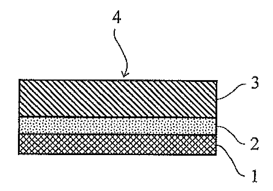
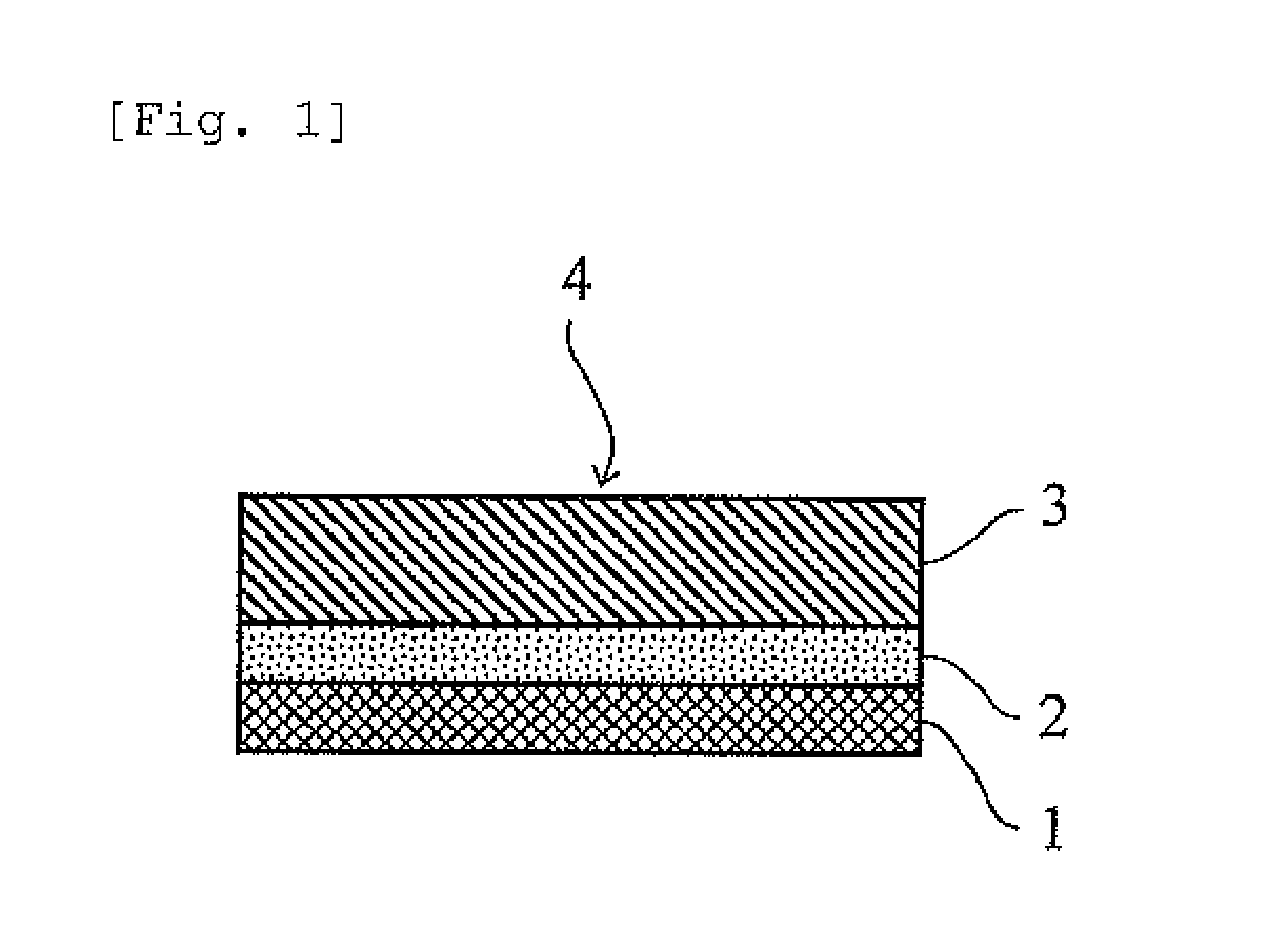
Laminate

a technology of laminates and laminates, applied in the field of laminates, can solve the problems of poor anchoring ability of resin layers, failure to protect laminates from “warping”, and failure to protect laminates from “warping”, and achieve the effects of satisfactory workability, less causes of transparency reduction, and high transparency

Inactive Publication Date: 2013-09-26
NITTO DENKO CORP
View PDF1 Cites 13 Cited by
  • Summary
  • Abstract
  • Description
  • Claims
  • Application Information

AI Technical Summary

Benefits of technology

[0017]A laminate according to an embodiment of the present invention is resistant to “warping” (suffers from less or no warping) and much less causes encapsulation failure when used for the encapsulation and surface protection of opto-electronic devices. This is because the laminate includes a thermoplastic resin layer and a substrate laminated or bonded to each other not through extrusion lamination but through the adhesiveness of a pressure-sensitive adhesive layer. The laminate surely has high transparency, because the laminate does not require the use of an anchor coating agent or another whitening-causing compound which is used upon extrusion lamination. In addition, the laminate according to the present invention serves both as a surface-protecting film and an encapsulant, thereby exhibits more satisfactory workability and less causes reduction in transparency than the case where a surface-protecting film and an encapsulant are used separately. The laminate, even when covering an opto-electronic device, much less causes reduction in photoelectric conversion efficiency of the opto-electronic device. The laminate therefore enables, for example, the encapsulation and surface protection of a colar cell while much less causing reduction in efficiency of sunlight utilization and enables the encapsulation and surface protection of an LED while much less causing reduction in brightness (intensity) of the LED.

Problems solved by technology

However, a laminate produced by this process, when cooled after the thermocompression bonding, suffers from “warping” due to cure shrinkage of the thermoplastic resin and, when used for the encapsulation and surface protection of opto-electronic devices, disadvantageously often causes encapsulation failure.
Even this lamination process, however, failed to protect the laminate from “warping”, although successively protecting it from wrinkling.
To produce a laminate by the extrusion lamination process, an anchor coating agent is generally applied to an interface between a thermoplastic resin layer and a PET film or another insulating film to improve anchoring capability between them, because such insulating film (e.g., PET film) and thermoplastic resin layer have poor anchoring capability with each other and often suffer from separation from each other.
The anchor coating agent, however, causes whitening (or blushing) to cause the laminate to have a lower luminous transmittance.
The resulting laminate, when used for the encapsulation and surface protection of opto-electronic devices, disadvantagously causes reduction in photoelectric conversion efficiency.

Method used


Image

  • Laminate
  • Laminate

Examples


preparation example 1

Preparation of Pressure-sensitive Adhesive Layer (1)

[0081]Initially, a mixture was prepared by blending 69 parts by weight of 2-ethylhexyl acrylate (2EHA), 30 parts by weight of 2-methoxyethyl acrylate (2MEA), 1 part by weight of 4-hydroxybutyl acrylate (4HBA), and 1 part by weight of acrylic acid (AA). The mixture was combined with photoinitiators, i.e., 0.05 part by weight of the trade name “IRGACURE 184” supplied by Ciba Specialty Chemicals Corporation and 0.05 part by weight of the trade name “IRGACURE 651” supplied by Ciba Specialty Chemicals Corporation, irradiated with an ultraviolet ray so as to have a viscosity of about 20 Pa·s as measured with a BH viscometer using a No. 5 rotor at 10 rpm and at a measurement temperature of 30° C., and thereby yielded a prepolymer composition in which part of the monomer components was polymerized.

[0082]The prepolymer composition (100 parts by weight) was combined with 0.01 part by weight of 1,3-bis(N,N-diglycidylaminomethyl)cyclohexane [t...

preparation example 2

Preparation of Pressure-Sensitive Adhesive Layer (2)

[0086]A pressure-sensitive adhesive layer (2) (with a separator) was prepared by the procedure of Preparation Example 1, except for using 1,6-hexamethylene diisocyanate [the trade name “DURANATE” supplied by Asahi Kasei Chemicals Corporation] instead of 1,3-bis(N,N-diglycidylaminomethyl)cyclohexane [the trade name “TETRAD C” supplied by MITSUBISHI GAS CHEMICAL COMPANY, INC.].

preparation example 3

Preparation of Thermoplastic Resin Layer (1)

[0087]An EVA [the trade name “EVAFLEX EV550” supplied by DUPONT-MITSUI POLYCHEMICALS CO., LTD, melting point: 89° C.] was heated and melted at a temperature of 180° C., extruded and molded through a T die and dried to form a thermoplastic resin layer (1) having a final thickness (thickness of the pressure-sensitive adhesive layer) of 400 μm. This had a total luminous transmittance of 90%.


PUM

PropertyMeasurementUnit
thicknessaaaaaaaaaa
peel strengthaaaaaaaaaa
luminous transmittanceaaaaaaaaaa

Abstract

Provided is a laminate including a thermoplastic resin layer and a substrate, which has superior transparency, is resistant to “warping”, and is advantageous for the encapsulation and surface protection of opto-electronic devices. The laminate includes a substrate; a thermoplastic resin layer having a thickness of more than 200 μm and less than or equal to 500 μm; and a pressure-sensitive adhesive layer lying between the substrate and thermoplastic resin layer and bonding them to each other, in which the thermoplastic resin layer has a 180-degree peel strength of 1.0 N / 25 mm or more with respect to the pressure-sensitive adhesive layer at 23° C. The laminate preferably has a total luminous transmittance of 80% or more.

Description

TECHNICAL FIELD[0001]The present invention relates to laminates including a thermoplastic resin and a substrate laminated to each other through a pressure-sensitive adhesive layer. The laminates according to the present invention are advantageously used for the encapsulation and surface protection of opto-electronic devices.BACKGROUND ART[0002]Solar cells, LEDs, and other opto-electronic devices each have a p-type semiconductor and an n-type semiconductor and utilize a photoelectric conversion activity in a depletion layer at a p-n junction. Specifically, solar cells can convert energy from sunlight directly to electrical energy; whereas LEDs can convert electrical energy to light energy.[0003]The p-type and n-type semiconductors, if coming in direct contact with the outside atmosphere, deteriorate in their functions. To avoid this, the semiconductors are preferably encapsulated with a transparent encapsulant (molding compound) and further coated with a transparent protective film f...

Claims


Application Information

Patent Timeline
Patent Type & Authority Applications(United States)
IPC IPC(8): H01L23/29
CPCH01L31/0481Y10T428/269H01L23/29Y02E10/50B32B27/308B32B7/12B32B27/08B32B27/32B32B27/36B32B2307/40B32B2457/20B32B2551/00H01L33/56C09J133/08H01L31/048B32B17/064H01L2924/0002C08F2220/1858C08F2220/281C08F220/20C08F220/06H01L2924/00B32B17/06C08F220/1808C08F220/281
Inventor NAKANISHI, TADATOSHIARIMITSU, YUKIOSHINTANI, TOSHIOKAWABE, SHIGEKIIKISHIMA, SHINSUKE
Owner NITTO DENKO CORP
Why Eureka
Try Eureka