Multi-band multi-antenna system and communiction device thereof

a multi-antenna system and communication device technology, applied in the direction of simultaneous aerial operations, elongated active element feeds, antennas, etc., can solve the problems of increasing the design complexity increasing the technical difficulty of isolation between the antennas, and increasing the design challenge of the multi-antenna system. achieve the effect of higher operating band and higher operating band

Active Publication Date: 2013-10-03
IND TECH RES INST
View PDF10 Cites 61 Cited by
  • Summary
  • Abstract
  • Description
  • Claims
  • Application Information

AI Technical Summary

Benefits of technology

[0012]The disclosure provides a multi-band multi-antenna system including a ground, a first antenna unit, a second antenna unit, a coupling conductor line and a grounding conductor line. The first antenna unit has a first conductor portion, a first low-pass filtering portion and a first extending conductor portion. The first conductor portion is electrically coupled to the ground through a first signal source, and the first low-pass filtering portion is electrically coupled between the first conductor portion and the first extending conductor portion. The first conductor portion forms a first higher band resonance path of the first antenna unit, and the first higher band resonance path generates a first higher operating band. The first conductor portion, the first low-pass filtering portion and the first extending conductor portion form a first lower band resonance path of the first antenna unit, and the first lower band resonance path generates a first lower operating band. The first higher and the first lower operating bands are respectively configured to transmit or receive electromagnetic signals of at least one communication system band. The second antenna unit has a second conductor portion, a second low-pass filtering portion and a second extending conductor portion. The second conductor portion is electrically coupled to the ground through a second signal source, and the second low-pass filtering portion is electrically coupled between the second conductor portion and the second extending conductor portion. The second conductor portion forms a second higher band resonance path of the second antenna unit, and the second higher band resonance path generates a second higher operating band. The second conductor portion, the second low-pass filtering portion and the second extending conductor portion form a second lower band resonance path of the second antenna unit, and the second lower band resonance path generates a second lower operating band. The second higher and the second lower operating bands are respectively configured to transmit or receive electromagnetic signals of at least one communication system band. The first lower and the second lower operating bands cover at least one same communication system band, and the first higher and the second higher operating bands cover at least one same communication system band. The coupling conductor line is disposed nearby the first antenna unit and the second antenna unit, and has a first coupling portion and a second coupling portion. There is a first coupling gap between first coupling portion and the first antenna unit, and there is a second coupling gap between the second coupling portion and the second antenna unit. The grounding conductor line is disposed between the first antenna unit and the second antenna unit, and is electrically connected to the ground.
[0013]The disclosure provides a communication device including a multi-band transceiver and a multi-band multi-antenna system. The multi-band transceiver is configured to serves as a signal source and is located on a ground. The multi-band multi-antenna system is electrically coupled to the multi-band transceiver, and includes a first antenna unit, a second antenna unit, a coupling conductor line and a grounding conductor line. The first antenna unit has a first conductor portion, a first low-pass filtering portion and a first extending conductor portion. The first low-pass filtering portion is electrically coupled between the first conductor portion and the first extending conductor portion, and the first conductor portion is electrically coupled to the multi-band transceiver. The first conductor portion forms a first higher band resonance path of the first antenna unit, and the first higher band resonance path generates a first higher operating band. The first conductor portion, the first low-pass filtering portion and the first extending conductor portion form a first lower band resonance path of the first antenna unit, and the first lower band resonance path generates a first lower operating band. The first higher and lower operating bands are respectively configured to transmit or receive electromagnetic signals of at least one communication system band. The second antenna unit has a second conductor portion, a second low-pass filtering portion and a second extending conductor portion. The second low-pass filtering portion is electrically coupled between the second conductor portion and the second extending conductor portion, and the second conductor portion is electrically coupled to the multi-band transceiver. The second conductor portion forms a second higher band resonance path of the second antenna unit, and the second higher band resonance path generates a second higher operating band. The second conductor portion, the second low-pass filtering portion and the second extending conductor portion form a second lower band resonance path of the second antenna unit, and the second lower band resonance path generates a second lower operating band. The second higher and the second lower operating bands are respectively configured to transmit or receive electromagnetic signals of at least one communication system band. The first lower and the second lower operating bands cover at least one same communication system band, and the first higher and the second higher operating bands cover at least one same communication system band. The coupling conductor line is disposed nearby the first antenna unit and the second antenna unit, and has a first coupling portion and a second coupling portion. There is a first coupling gap between the first coupling portion and the first antenna unit, and there is a second coupling gap between the second coupling portion and the second antenna unit. The grounding conductor line is disposed between the first antenna unit and the second antenna unit, and is electrically connected to the ground.

Problems solved by technology

Therefore, a design challenge of the MIMO multi-antenna system is increased.
When a plurality of antennas having a same operating band are designed in a device with a limited space, if each of the antennas is required to achieve a demand of multi-band operation, problems such as multi-band decoupling may increase design complexity of the multi-antenna system.
Therefore, the antenna of the LTE700 band requires a larger resonance size for implementation, so that in the device with the limited space, a space between the antennas is shortened, which leads to increasing technical difficulty in isolation between the antennas.
However, this method is applied in single band energy decoupling rather than multi-band energy decoupling.
However, the grounding metal structure or the slot would excite strong induced surface currents on the ground, and when the induced surface current are generated in a longer wavelength band, it may decrease the impedance matching of the two adjacent antennas.

Method used


Image

  • Multi-band multi-antenna system and communiction device thereof
  • Multi-band multi-antenna system and communiction device thereof
  • Multi-band multi-antenna system and communiction device thereof

Examples


Embodiment Construction

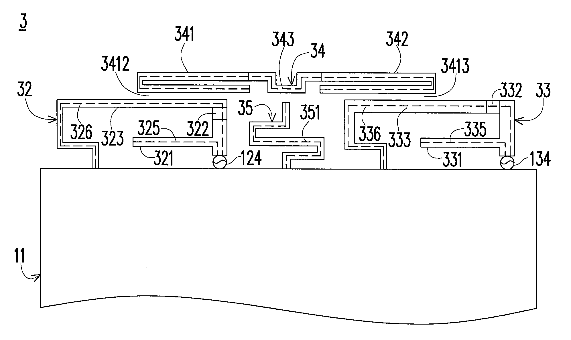
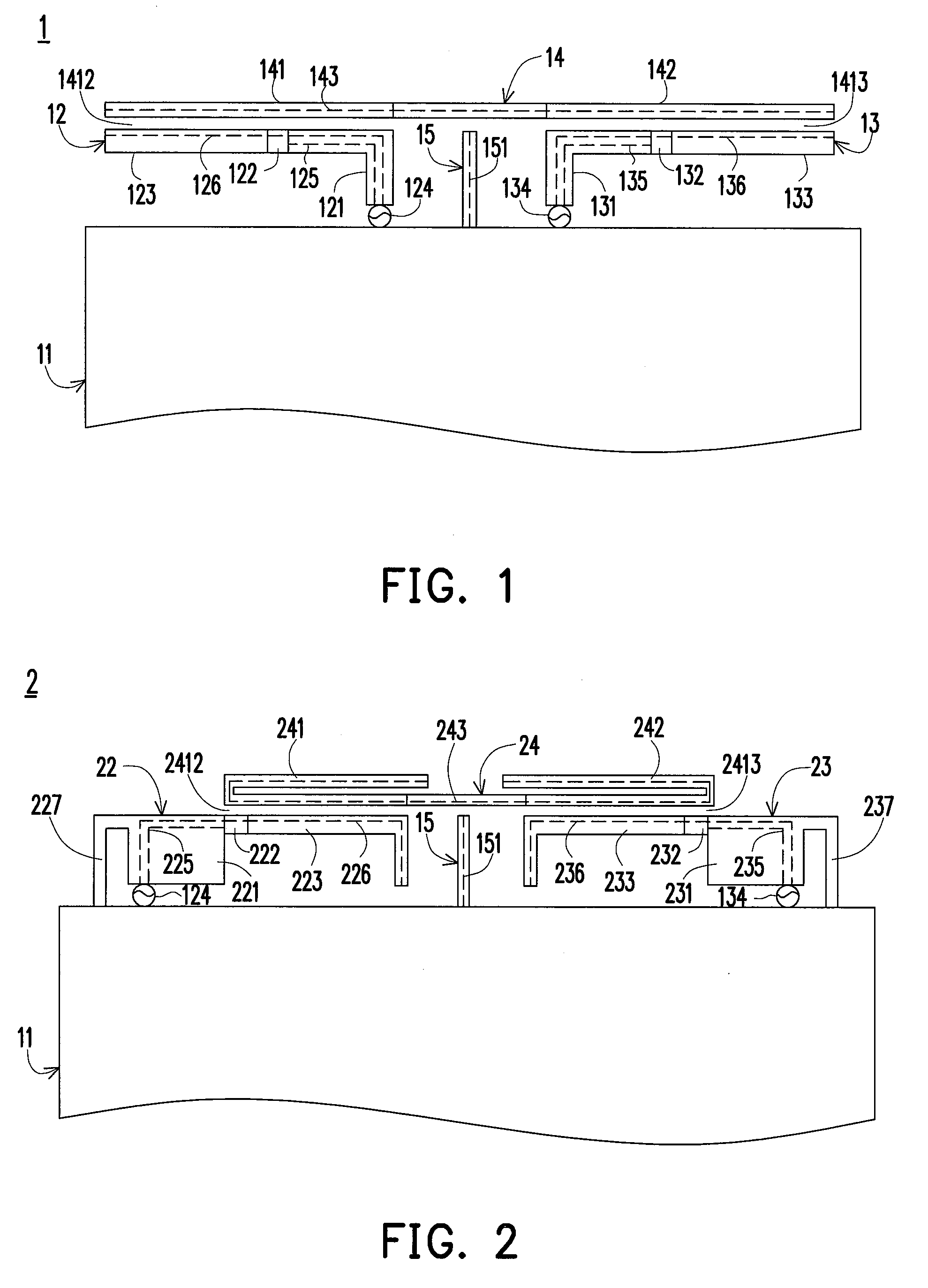
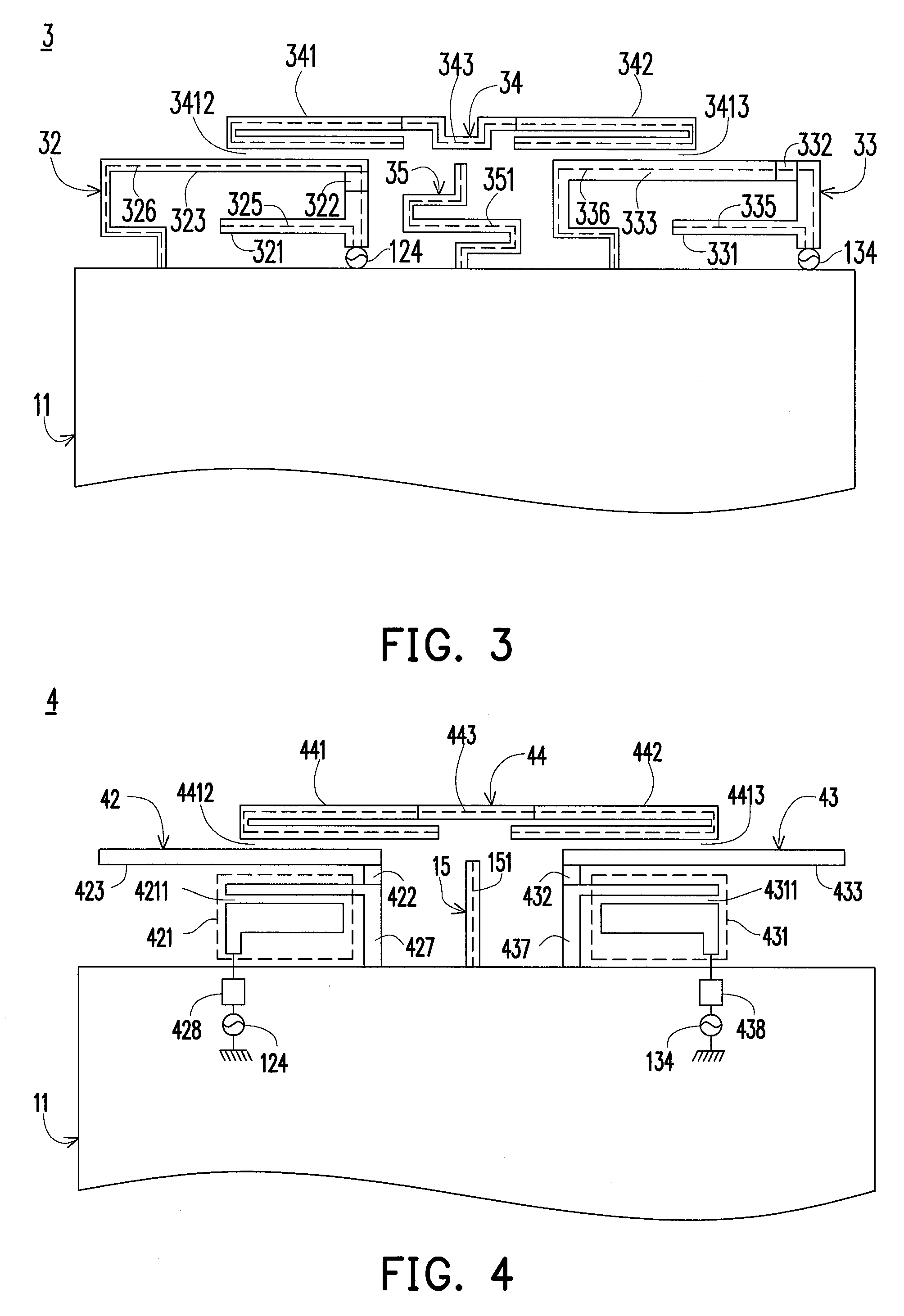
[0033]Below, exemplary embodiments will be described in detail with reference to accompanying drawings so as to be easily realized by a person having ordinary knowledge in the art. The inventive concept may be embodied in various forms without being limited to the exemplary embodiments set forth herein. Descriptions of well-known parts are omitted for clarity, and like reference numerals refer to like elements throughout.

[0034]The disclosure provides a plurality of exemplary embodiments illustrating multi-band multi-antenna systems and communication devices thereof. The exemplary embodiments may be applied in various communication devices, for example, a mobile communication device, a wireless communication device, a mobile computing device, a computer system, or the exemplary embodiments may be applied in telecommunication equipment, network equipment or peripheral equipment of a computer or a network.

[0035]A plurality of exemplary embodiments of the disclosure provides technical s...


PUM


Abstract

A multi-band multi-antenna system and a communication device thereof are provided. The multi-band multi-antenna system includes at least one ground, two antenna units, a coupling conductor line and a grounding conductor line. Both of the two antenna units have at least one conductor portion, a low-pass filtering portion and an extending conductor portion. Each antenna unit generates at least one higher and lower operating bands. The low-pass filtering portion is electrically coupled between the conductor portion and the extending conductor portion, and effectively decreases dependent relationship between the higher and lower operating bands. The coupling conductor line is disposed nearby the two antenna units and has a first coupling portion and a second coupling portion. The grounding conductor line is disposed between the two antenna units and connected to the ground.

Description

CROSS-REFERENCE TO RELATED APPLICATION[0001]This application claims the priority benefit of Taiwan application serial no. 101111861, filed on Apr. 3, 2012. The entirety of the above-mentioned patent application is hereby incorporated by reference herein and made a part of this specification.BACKGROUND[0002]1. Field of the Disclosure[0003]The disclosure relates to a multi-antenna structure and a communication device thereof.[0004]2. Description of Related Art[0005]The increasing demand in signal quality, reliability and transmission speed of wireless communication signals result in multi-antenna systems being developed, for example, a pattern switchable or beam-steering antenna system or a multi-input multi-output (MIMO) antenna system. For example, the MIMO antenna technique (IEEE 802.11n) of a wireless local area network (WLAN) system band (2400-2484 MHz, 84 MHz) has been successfully applied in products such as laptops, handheld communication devices or wireless access points, and...

Claims


Application Information

Patent Timeline
Patent Type & Authority Applications(United States)
IPC IPC(8): H01Q21/28
CPCH01Q5/321H01Q5/378H01Q21/28H01Q9/42H01Q5/40
Inventor LI, WEI-YUCHEN, WEI-JIWU, CHUN-YIH
Owner IND TECH RES INST
Why Eureka
Try Eureka