Chemical oxygen generator with chemical cores arranged in parallel

a technology of chemical oxygen and generator, which is applied in the field of chemical oxygen generators, can solve the problems of increasing the length of the chemical core, the difficulty of increasing the generator length, and the longer the operation time, so as to achieve the effect of increasing the length of the chemical oxygen generator

Active Publication Date: 2013-10-03
BE AEROSPACE INCORPORATED
View PDF5 Cites 4 Cited by
  • Summary
  • Abstract
  • Description
  • Claims
  • Application Information

AI Technical Summary

Benefits of technology

[0013]A chemical core transition section is disposed between and immediately adjacent to and contiguous with the second end of the first one of the plurality of parallel sequentially connected chemical core sections and the first end of the second one of the plurality of parallel sequentially connected chemical core sections, to insure that the reaction front propagates from the second end of the first one of the plurality of parallel sequentially connected chemical core sections to the second end of the second one of the plurality of parallel sequentially connected chemical core sections when the reaction front reaches the second end of the first one of the plurality of parallel sequentially connected chemical core sections. In a presently preferred aspect, the transition section comprises a highly reactive oxygen generating composition layer. In another presently preferred aspect, the transition section is oriented at approximately 45 degrees to a longitudinal axis of the chemical oxygen generator housing. In another presently preferred aspect, the transition section is configured to force the reaction front to travel from the second end of the first one of the plurality of parallel chemical core sections to the second end of the second one of the plurality of parallel chemical core sections orthogonally to the longitudinal axis of the chemical oxygen generator housing. In the chemical core arrangement of this invention, the reaction front moves along the first of the parallel core sections, and after the first section has been consumed, the reaction front moves to the next core section in parallel through the transition section, and proceeds from the outlet end toward the ignition end, so that the reaction front velocity and duration of operation of the chemical oxygen generator can be increased without increasing the length of the chemical oxygen generator.

Problems solved by technology

However, since the reaction front needs to move at a certain linear rate, the length of the chemical core has to be increased when a relatively longer duration of operation is needed.
Due to the limited space available in aircraft, it is difficult to increase the generator length beyond the length of the typical space envelope provided for an oxygen generator, so that heavier cores are typically used in such conventional chemical oxygen generators to insure the chemical cores have sufficient duration.
The honeycomb type separator occupies a substantial volume and increases weight of the chemical candle, and is not suitable for aviation use.
If the reaction front moves too slowly, the reaction becomes less controllable, and may stop.
In order to maintain a minimum reaction front linear velocity and meet requirements for a duration of operation of the chemical oxygen generator, typically it has been necessary to increase the weight or length of the chemical core of the chemical oxygen generator, resulting in an increase in the weight or length of the chemical oxygen generator.

Method used


Image

  • Chemical oxygen generator with chemical cores arranged in parallel
  • Chemical oxygen generator with chemical cores arranged in parallel
  • Chemical oxygen generator with chemical cores arranged in parallel

Examples


Embodiment Construction

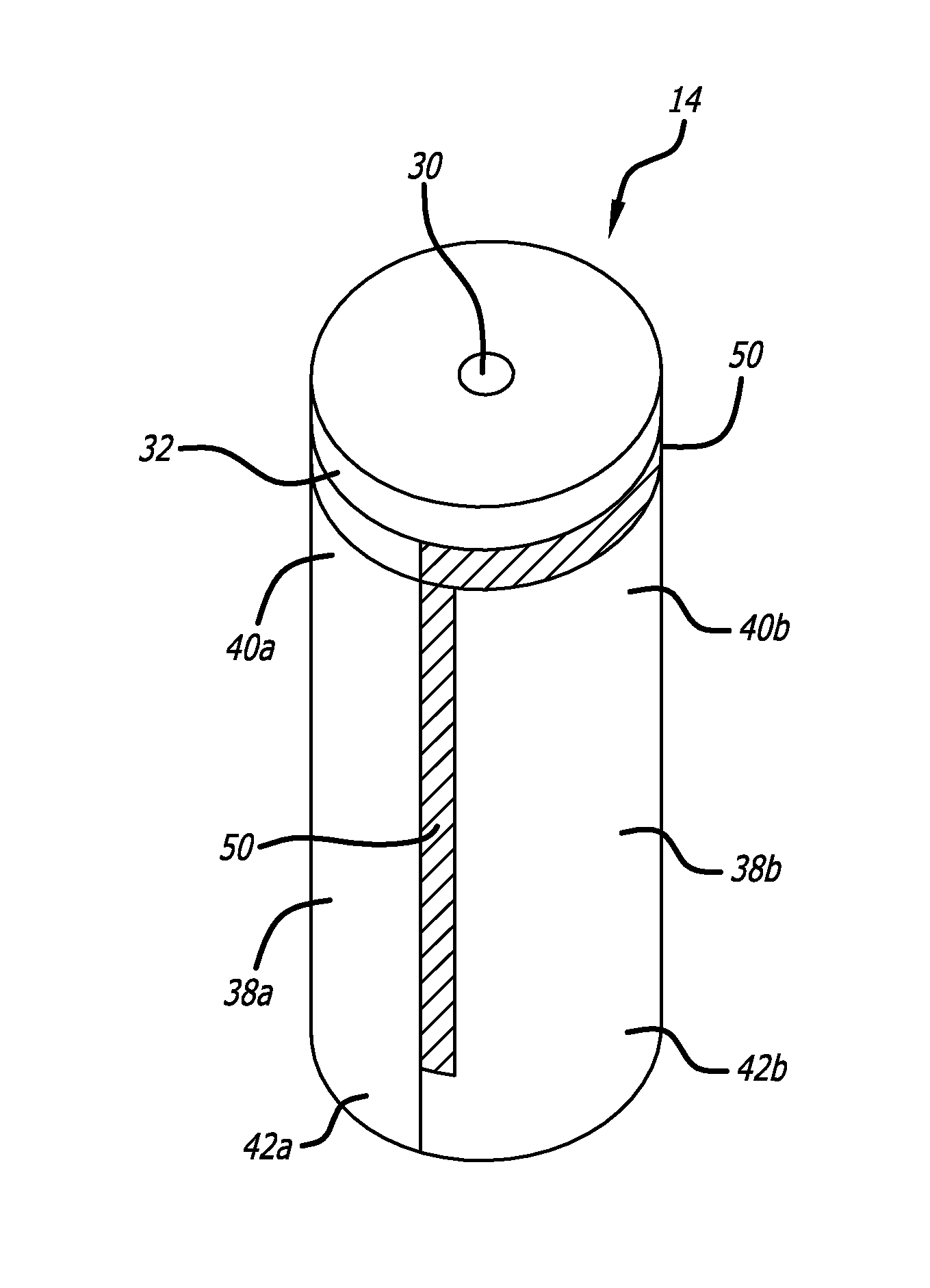
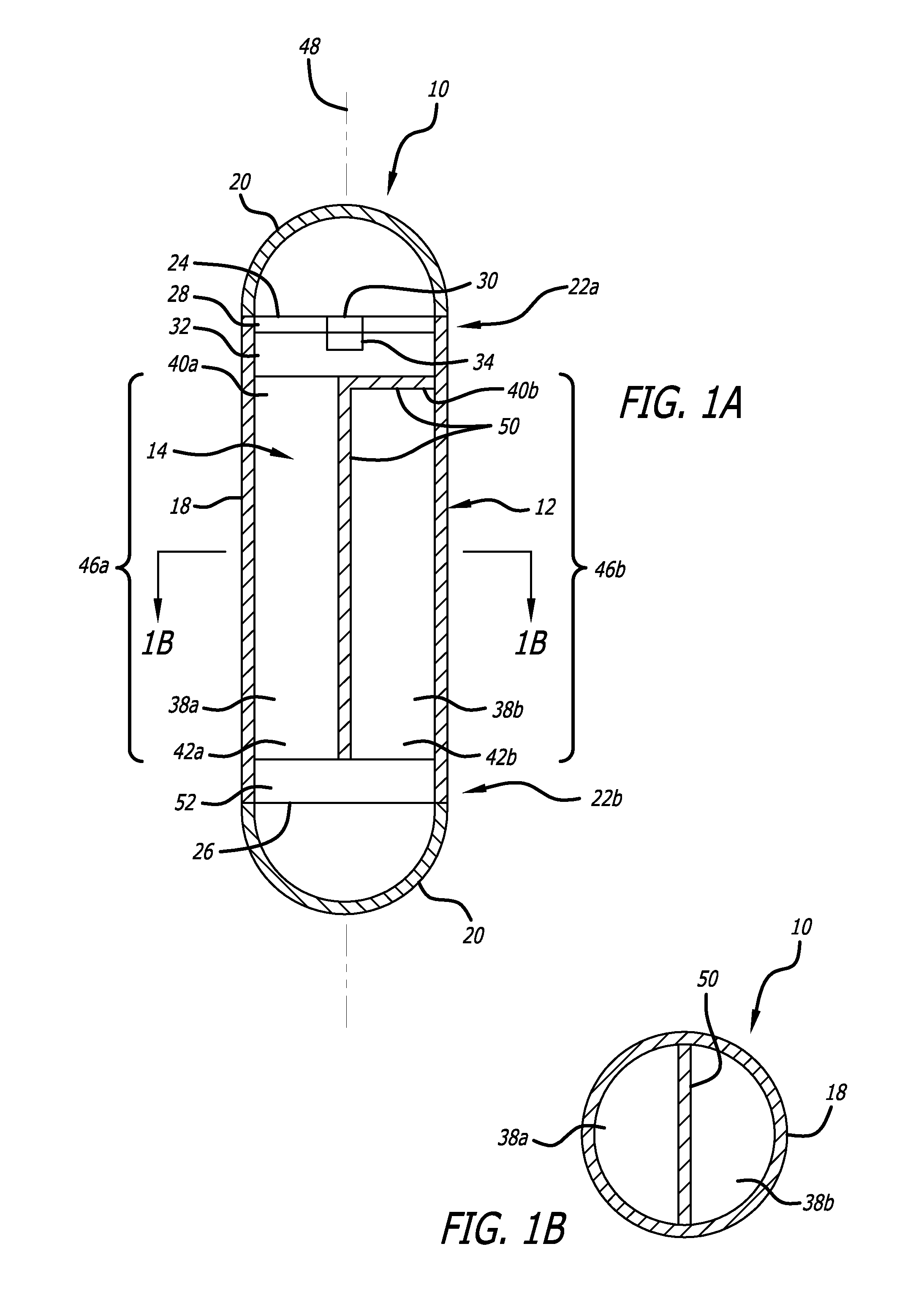
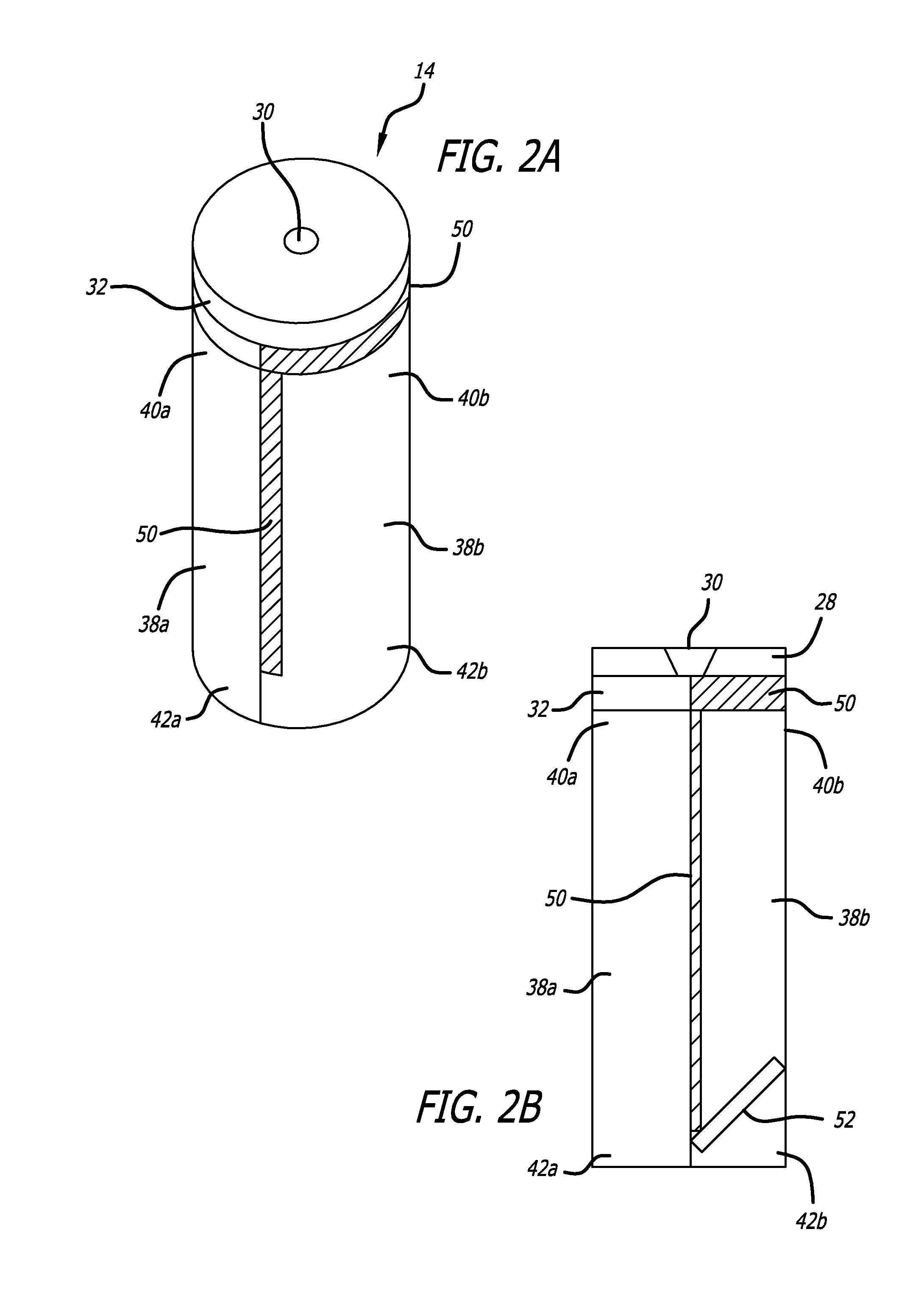
[0021]Referring to the drawings, which are provided by way of example, and not by way of limitation, the present invention provides for a chemical oxygen generator including a plurality of parallel sequentially connected chemical core sections that extend the duration of operation of the chemical oxygen generator without increasing the weight or length of the generator. The present invention accordingly provides for a chemical oxygen generator 10 including a chemical oxygen generator housing 12 containing a chemical core assembly 14 including one or more oxygen generating compositions for producing a supplemental breathable gas when a reaction front propagates through the oxygen generating composition. The chemical oxygen generator housing is typically formed of stainless steel, and can be formed by wrapping the chemical core assembly in a stainless steel sheet, perforated stainless steel sheet, or stainless steel wire mesh, for example, to form the main generally cylindrical body 1...


PUM


Abstract

A chemical oxygen generator includes multiple parallel sequentially connected chemical core sections that extend the duration of operation of the chemical oxygen generator. An end of a first core section is contiguous with a chemical core high reactivity section, and a thermal insulation layer is disposed between an end of a second core section and the chemical core ignition plate, as well as between the bodies of the first and second core sections. A chemical core transition section is disposed between the other end of the first core section and the second core section, to insure that the reaction front propagates properly.

Description

BACKGROUND OF THE INVENTION[0001]This invention relates generally to chemical oxygen generators for civilian and military airplanes to provide supplemental oxygen, and more particularly relates to a chemical oxygen generator having a chemical oxygen generating core assembly composed of multiple sections, with at least two of the sections arranged in parallel so that a duration of operation of the chemical oxygen generator can be extended without increasing the length of the generator.[0002]Chemical oxygen generators are typically used in situations requiring the generation of supplemental oxygen, such as in aviation and in submarines, for example, and in other similar settings where it is useful to furnish a convenient and reliable supply of oxygen gas of breathable quality. Chemical oxygen generating compositions based upon the decomposition of alkali metal chlorates or perchlorates have long been used as an emergency source of breathable oxygen in passenger aircraft, for example.[...

Claims


Application Information

Patent Timeline
Patent Type & Authority Applications(United States)
IPC IPC(8): A62B7/08
CPCA62B7/08A62B7/14A62B21/00C01B13/0296C01B13/0218C01B13/0233C01B13/02
Inventor MAROSKE, GERALDERNST, RAINERZHANG, YUNCHANGKSHIRSAGAR, GIRISH S.
Owner BE AEROSPACE INCORPORATED
Why Eureka
Try Eureka