Pumping mechanism, distributing valve thereof and concrete pumping machine

a technology of pumping mechanism and distributing valve, which is applied in the direction of machines/engines, positive displacement liquid engines, transportation and packaging, etc., can solve the problems of increasing the energy consumption lowering the driving etc., to reduce the driving force, increase the pumping pressure and improve the sealing performance of the distributing valv

Inactive Publication Date: 2013-10-10
HUNAN SANY INTELLIGENT CONTROL EQUIP CO LTD & SANY HEAVY IND
View PDF7 Cites 5 Cited by
  • Summary
  • Abstract
  • Description
  • Claims
  • Application Information

AI Technical Summary

Benefits of technology

[0021]In a further technical solution, the valve casing of the distributing valve further comprises a valve body, a seal adjustment plate and an adjustment assembly adjusting the matching gap between the outer side faces of the cutting plates and the sealing face; the sealing gap and the friction force of the cutting portion can be adjusted via the adjustment assembly; then, according to pumping needs, the distributing valve can adapt to different pumping pressures. When a material needs to be pumped to a high or far location, by way of the adjustment assembly, the matching gap between the outer side faces of the cutting plates and the sealing face can be reduced, and the sealing performance of the distributing valve is improved, so as to increase the pumping pressure of the pumping mechanism; when a material needs to be pumped to a low or near location, the matching gap between the outer side faces of the cutting plates and the sealing face can be increased by way of the adjustment assembly, so as to decrease the driving force needed by driving the rotation of the valve core, improve the driving performance of the distributing valve, and lower the energy consumption of the distributing valve.
[0022]In a further technical solution, when the outer side faces of the cutting plates match the inner side faces of the seal adjustment plates, the corresponding seal adjustment plate and the cutting plate extend in one plane; therefore, the cutting plates can better match the seal adjustment plates, and the matching gap between the two can be conveniently adjusted.
[0023]In a further technical solution, the valve casing comprises three said seal adjustment plates, and the inner side faces of the three seal adjustment plates form the sealing face; in the first state of the distributing valve, the outer side faces of two said cutting plates are respectively sealedly matched with the inner side face of a first seal adjustment plate and the inner side face of a second seal adjustment plate; and in the second state of the distributing valve, the outer side faces of two said cutting plates are respectively sealedly matched with the inner side face of the second seal adjustment plate and the inner side face of a third seal adjustment plate. Thus, the adjustment assembly can adjust the positions of the inner side faces of the three seal adjustment plates, so that the inner side faces of the three seal adjustment plates are located within one arc-shaped face, thereby better ensuring the reliability of the rotatable sealed matching between the sealing face of the valve casing and the outer side faces of the respective cutting plates.
[0024]In a further technical solution, the peripheral face of the upper end portion of the valve core is in rotating matching with the inner wall face of the upper port of the valve casing; the upper opening of the adjustment plate groove is located within the upper surface of the valve body, and the seal adjustment plates can be mounted into the adjustment plate groove from the upper opening. In this technical solution, the seal adjustment plates can mounted via the upper opening of the adjustment plate groove; as the thickness of the cutting plate is not larger than that of the seal adjustment plate, the valve core and its cutting plate can also be mounted into the pumping chamber of the valve casing through the upper port of the valve casing and the adjustment plate groove, and then the mounting and maintenance of the distributing valve are made convenient.
[0025]In a further technical solution, the peripheral face of the lower end portion of the valve core is in rotating matching with the inner wall face of the lower port of the valve casing; and the valve body is integrally formed. Based on the above technical effect, this technical solution can maintain a simple structure of the valve body; meanwhile, the integrally formed valve body increases the rigidity of the valve casing or the valve body, enhances the overall strength of the distributing valve, so that the distributing valve can meet the need of a high pumping pressure, and the pumping ability of the pumping mechanism comprising the distributing valve is improved.
[0026]In a further technical solution, the cutting plate comprises a cutting plate body and a hard alloy sheet fixed on the outer side face of the cutting plate body, and the outer surface of the hard alloy sheet forms the outer side face of the cutting plate; or, the seal adjustment plate comprises a plate body and a hard alloy sheet fixed at the outer side face of the plate body, and the surface of the hard alloy sheet towards the valve core forms the inner side face of the seal adjustment plate. While ensuring the above technical effects, this technical solution can improve the wearing resistance of the cutting portion of the distributing valve and prolong the service life of the distributing valve.

Problems solved by technology

While the enhancement of the sealing performance will increase the driving force required by driving the rotation of the valve core, lower the driving performance of the distributing valve and increase the energy consumption of the distributing valve.

Method used


Image

  • Pumping mechanism, distributing valve thereof and concrete pumping machine
  • Pumping mechanism, distributing valve thereof and concrete pumping machine
  • Pumping mechanism, distributing valve thereof and concrete pumping machine

Examples


Embodiment Construction

[0035]The present invention will be detailed hereinafter taken in combination with the drawings, and the following description are just demonstrative and explanatory, and shall not be understood as limitations in any way on the scope of protection of the present invention.

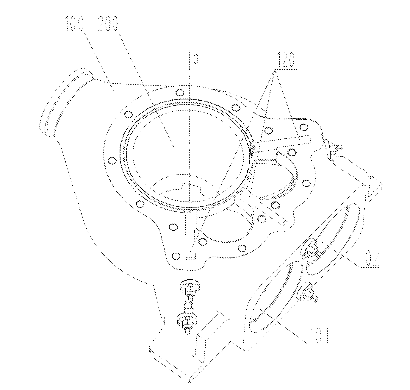
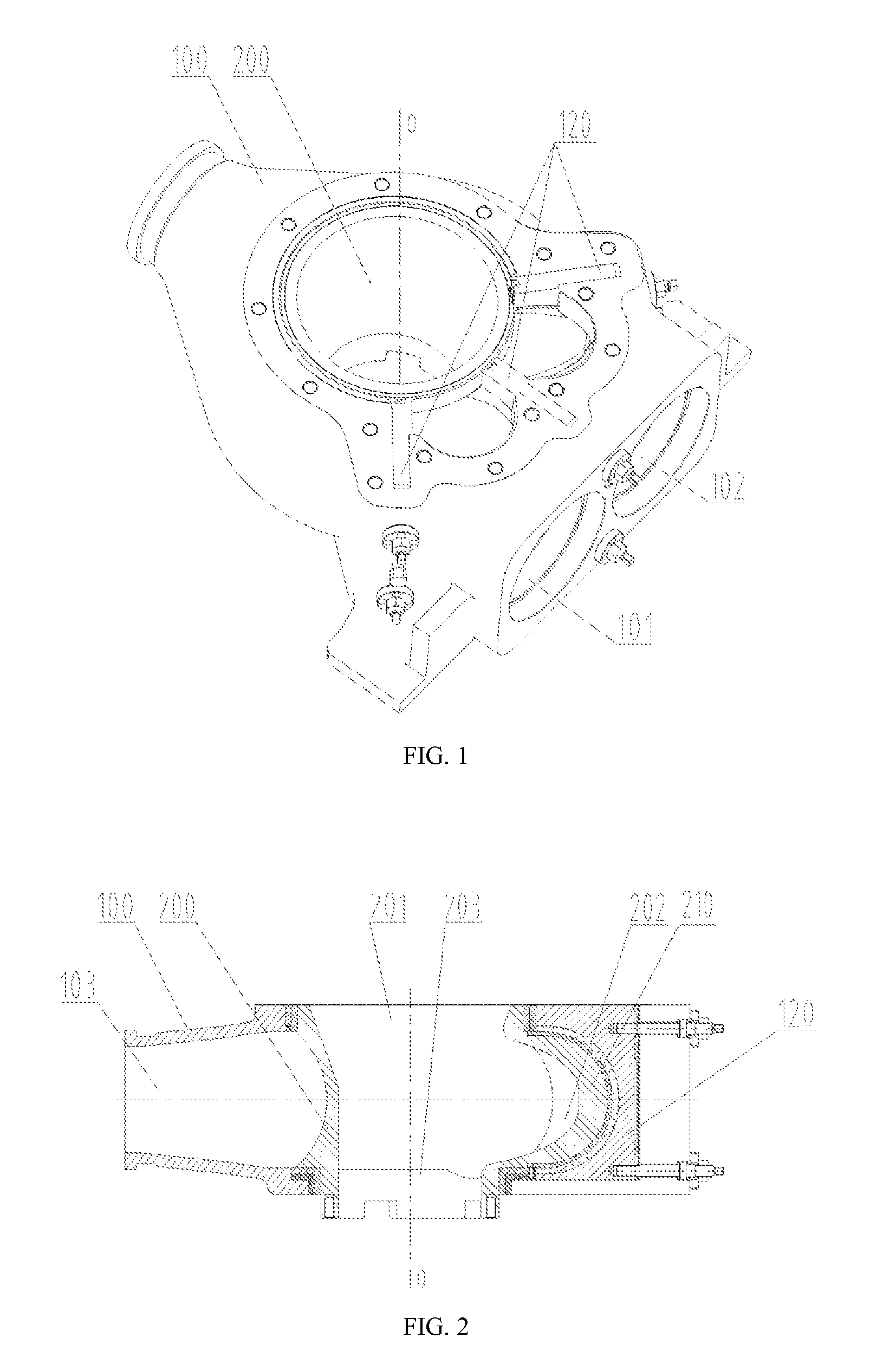
[0036]Referring to FIGS. 1-3, FIG. 1 is a schematic diagram of the three-dimensional structure of the distributing valve provided by the present invention; FIG. 2 is a schematic diagram of the sectional structure of the distributing valve shown in FIG. 1; and FIG. 3 is a schematic diagram of the three-dimensional assembling structure of the distributing valve shown in FIG. 1.

[0037]The distributing valve of the pumping mechanism provided by the present invention comprises a valve casing 100 and a valve core 200. In combination with FIGS. 1 and 3, the valve casing 100 is in a case-shape structure and is formed with a pumping chamber therein. The valve casing 100 comprises a discharge hole 103 throughout the casing wa...


PUM


Abstract

A pumping mechanism and the distributing valve thereof and a concrete pumping machine are disclosed. The distributing valve includes a valve casing (100) and a valve core (200) located in the pumping chamber of the valve casing. The valve core is rotatably connected to the valve casing, thus forming a main rotating axis (O). The valve casing has a discharge hole (103) throughout the casing wall, a first suction hole (101) and a second suction hole (102). The valve core has a distributing port (202) and a feed port (201) communicated with a material container. A pumping channel is formed between the peripheral face of the valve core and the inner wall face of the pumping chamber. The peripheral face of the valve core is provided with two cutting plates (210) protruding from two sides of the distributing port respectively. The outer side faces of the two cutting plates are rotatably sealedly matched with the sealing face of the valve casing. In a first state, the distributing port is communicated with the first suction hole through the space between the two cutting plates. In a second state, the distributing port is communicated with the second suction hole through the space between the two cutting plates. The distributing valve has a smaller matching area for cutting so as to ensure better sealing performance whilst have higher driving performance.

Description

[0001]The present application claims the priority to the Chinese patent application No. 201110103005.3 filed with the State Intellectual Property Office of the PRC on Apr. 22, 2011 and entitled “A Pumping Mechanism and the Distributing Valve Thereof and A Concrete Pumping Machine”, which is incorporated herein by reference in its entirety.FIELD OF THE INVENTION[0002]The present invention relates to a technology of pumping a viscous material, particularly concrete, and especially to the distributing valve of a pumping mechanism, and also relates to a pumping mechanism comprising the distributing valve, and a concrete pumping machine comprising the pumping mechanism.BACKGROUND OF THE INVENTION[0003]Currently, during conveying concrete and other viscous materials, usually a pumping mechanism is used to pump the materials to convey concrete or other viscous materials from one position to another predetermined position, to achieve a predetermined object. The pumping mechanism usually com...

Claims


Application Information

Patent Timeline
Patent Type & Authority Applications(United States)
IPC IPC(8): F04D13/00
CPCF04D13/00B65G53/32F16K11/0873F16K11/072F16K11/08B65G53/56Y10T137/85986Y10T137/87812
Inventor LIANG, YONGJIAOLIU, GUIFENG
Owner HUNAN SANY INTELLIGENT CONTROL EQUIP CO LTD & SANY HEAVY IND
Why Eureka
Try Eureka