Apparatus and method for implementing a multi-level memory hierarchy having different operating modes

a multi-level memory and operating mode technology, applied in the field of computer systems, can solve the problems of not preventing the user from accessing the platform, and affecting the overall power and cost of the electronic system, and affecting the user's experien

Active Publication Date: 2013-10-10
SK HYNIX NAND PROD SOLUTIONS CORP
View PDF4 Cites 82 Cited by
  • Summary
  • Abstract
  • Description
  • Claims
  • Application Information

AI Technical Summary

Problems solved by technology

In addition, memory power and cost have become a significant component of the overall power and cost, respectively, of electronic systems.
Since high cycle count blocks are most likely to wear out in this manner, wear leveling spreads writes across the far memory cells by swapping addresses of high cycle count blocks with low cycle count blocks.
This allows an external resource (e.g., a server on a network) to determine the trustworthiness of the platform but does not prevent access to the platform by the user.
However, certain PCM characteristics such as asymmetrical Read-vs-Write performance, write cycling endurance limits, as well as its non-volatile nature makes it challenging to directly replace DRAM without incurring major software changes.
Such an MSC is very large compared to conventional caches found in current processor / system architectures.
The cost of storing and looking up the MSC tags can be a significant impediment to building large caches.
Under certain conditions, storing tags with the data may create an issue for writes.
Such a read before every write could become costly.
Typically, the majority of blocks do not cycle, but high cycle count blocks are most likely to fail and wear leveling swaps addresses of high cycle count blocks with low cycle count blocks.
However, some applications are not hardware cache-friendly and, as such, would benefit from alternate ways to use such memory.

Method used


Image

  • Apparatus and method for implementing a multi-level memory hierarchy having different operating modes
  • Apparatus and method for implementing a multi-level memory hierarchy having different operating modes
  • Apparatus and method for implementing a multi-level memory hierarchy having different operating modes

Examples


Embodiment Construction

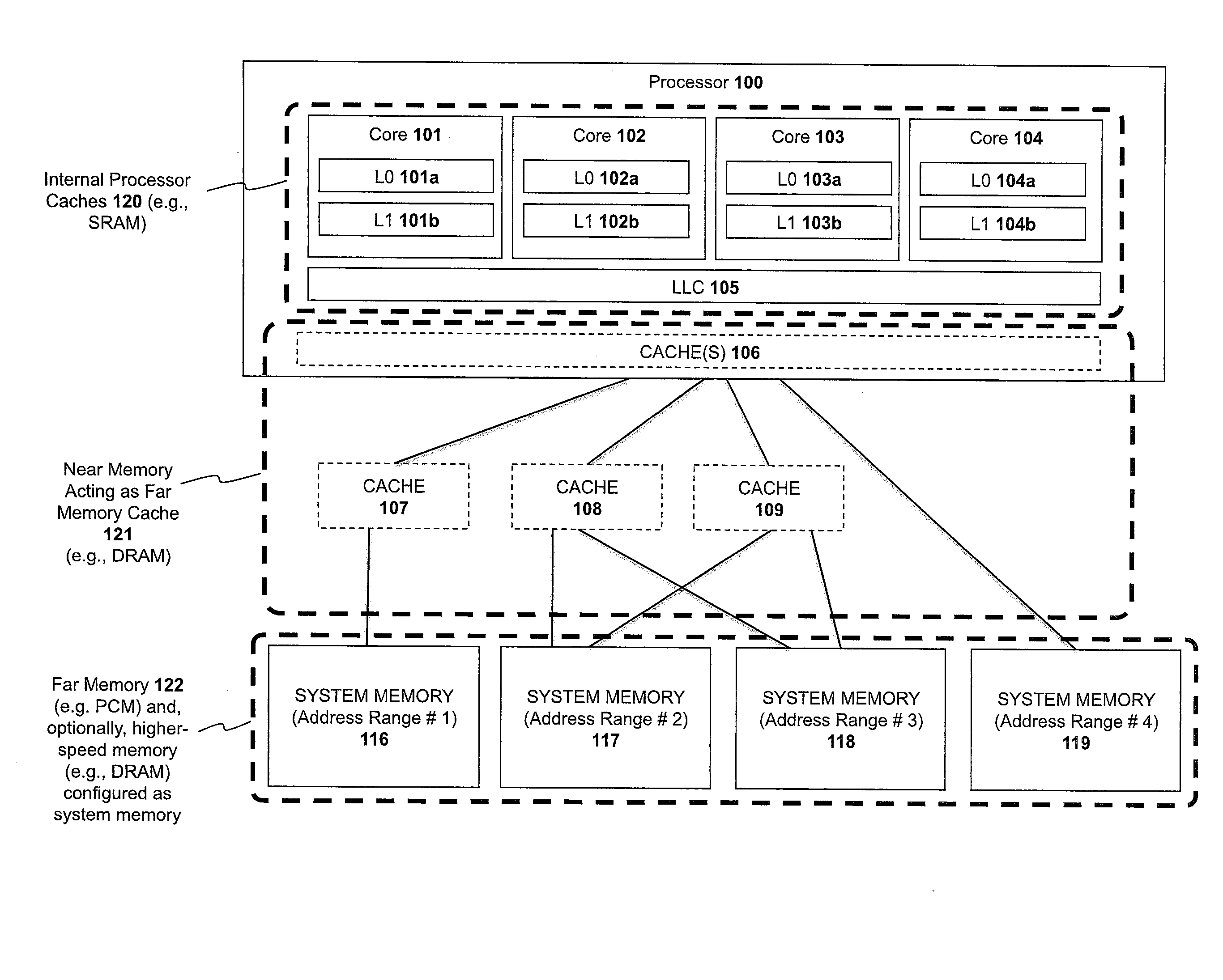
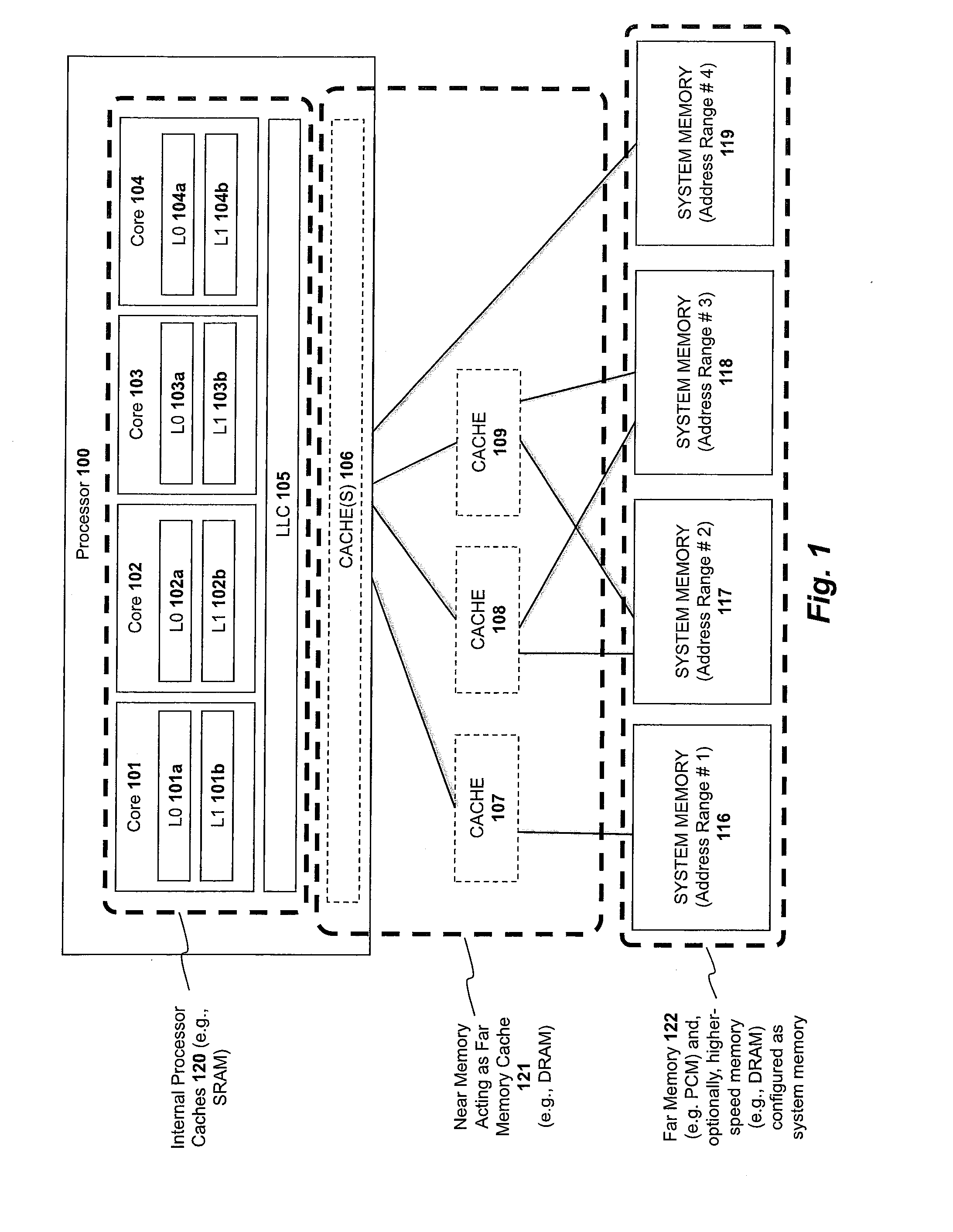
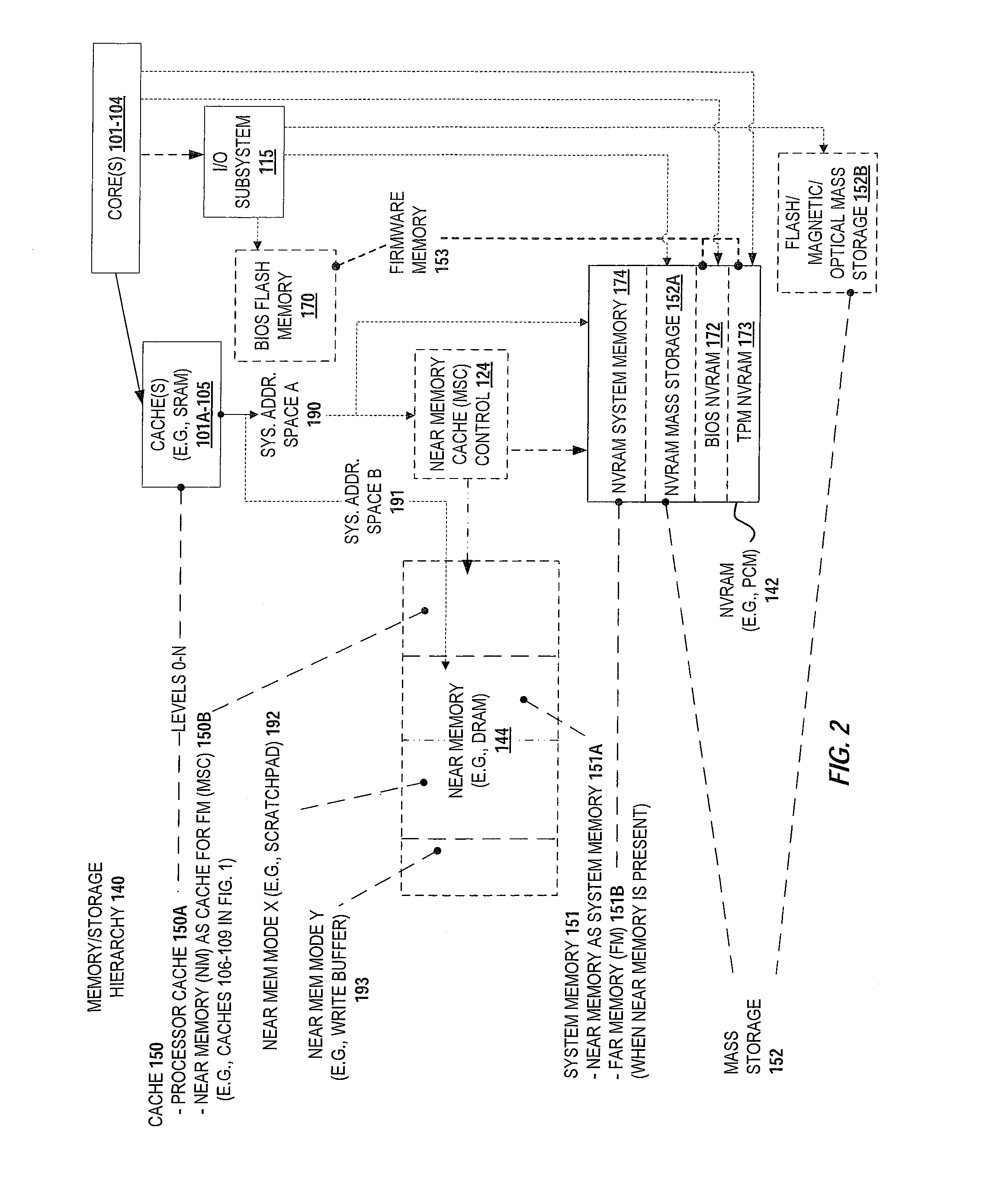
[0037]In the following description, numerous specific details such as logic implementations, opcodes, means to specify operands, resource partitioning / sharing / duplication implementations, types and interrelationships of system components, and logic partitioning / integration choices are set forth in order to provide a more thorough understanding of the present invention. It will be appreciated, however, by one skilled in the art that the invention may be practiced without such specific details. In other instances, control structures, gate level circuits and full software instruction sequences have not been shown in detail in order not to obscure the invention. Those of ordinary skill in the art, with the included descriptions, will be able to implement appropriate functionality without undue experimentation.

[0038]References in the specification to “one embodiment,”“an embodiment,”“an example embodiment,” etc., indicate that the embodiment described may include a particular feature, st...


PUM


Abstract

A system and method are described for integrating a memory and storage hierarchy including a non-volatile memory tier within a computer system. In one embodiment, PCMS memory devices are used as one tier in the hierarchy, sometimes referred to as “far memory.” Higher performance memory devices such as DRAM placed in front of the far memory and are used to mask some of the performance limitations of the far memory. These higher performance memory devices are referred to as “near memory.” In one embodiment, the “near memory” is configured to operate in a plurality of different modes of operation including (but not limited to) a first mode in which the near memory operates as a memory cache for the far memory and a second mode in which the near memory is allocated a first address range of a system address space with the far memory being allocated a second address range of the system address space, wherein the first range and second range represent the entire system address space.

Description

BACKGROUND[0001]1. Field of the Invention[0002]This invention relates generally to the field of computer systems. More particularly, the invention relates to an apparatus and method for implementing a multi-level memory hierarchy.[0003]2. Description of the Related Art[0004]A. Current Memory and Storage Configurations[0005]One of the limiting factors for computer innovation today is memory and storage technology. In conventional computer systems, system memory (also known as main memory, primary memory, executable memory) is typically implemented by dynamic random access memory (DRAM). DRAM-based memory consumes power even when no memory reads or writes occur because it must constantly recharge internal capacitors. DRAM-based memory is volatile, which means data stored in DRAM memory is lost once the power is removed. Conventional computer systems also rely on multiple levels of caching to improve performance. A cache is a high speed memory positioned between the processor and syste...

Claims


Application Information

Patent Timeline
Patent Type & Authority Applications(United States)
IPC IPC(8): G06F12/08
CPCG11C7/1045G06F12/0811G06F12/0808G11C13/0004G06F12/0246G06F2212/205G06F12/0815G06F2212/7201G06F12/0893G06F12/0638G06F2212/7204Y02D10/00G06F12/0806G06F12/0888G06F2212/283G06F2212/6046G06F2212/621G11C7/1072G11C14/0045
Inventor RAMANUJAN, RAJ K.AGARWAL, RAJATHINTON, GLENN J.
Owner SK HYNIX NAND PROD SOLUTIONS CORP
Why Eureka
Try Eureka