Digital MicroFluidics System with Swappable PCB's

a microfluidics and digital technology, applied in the direction of fluid pressure measurement, liquid/fluent solid measurement, peptide measurement, etc., can solve the problem that automatic systems are not designed to be portabl

Active Publication Date: 2013-10-17
TECAN TRADING AG
View PDF6 Cites 35 Cited by
  • Summary
  • Abstract
  • Description
  • Claims
  • Application Information

AI Technical Summary

Benefits of technology

[0032]The disposable cartridges can be configured as simple consumables that provide the working layers and the gap between and for carrying out the assay defined by the swappable electrode boards. The working layers of the cartridge prevent the swappable electrode boards and the entire digital microfluidics system from being contaminated.

Problems solved by technology

These automated systems are not designed to be portable and typically require larger volumes of liquids (microliter to milliliter) to process.

Method used


Image

  • Digital MicroFluidics System with Swappable PCB's
  • Digital MicroFluidics System with Swappable PCB's
  • Digital MicroFluidics System with Swappable PCB's

Examples


first embodiment

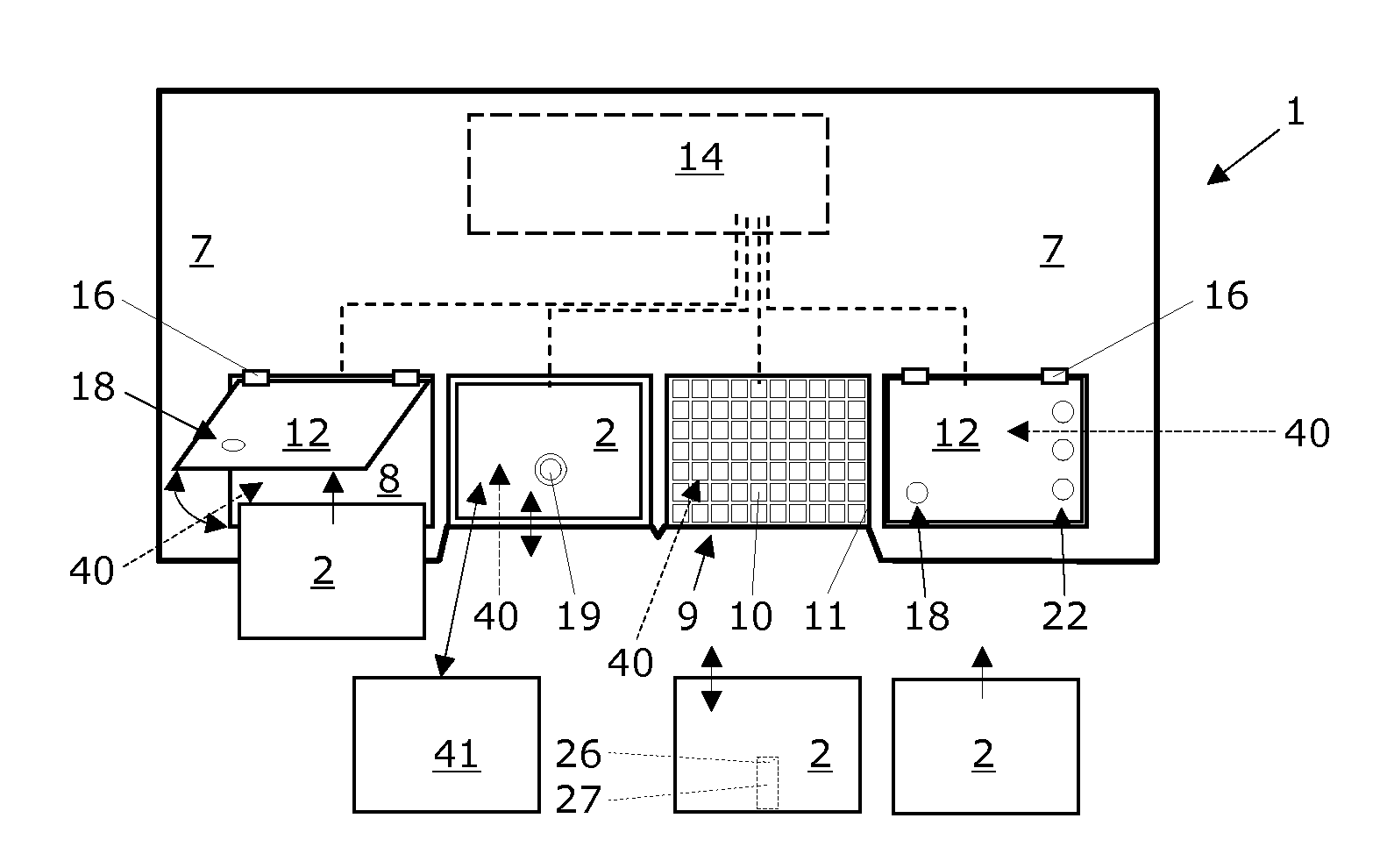
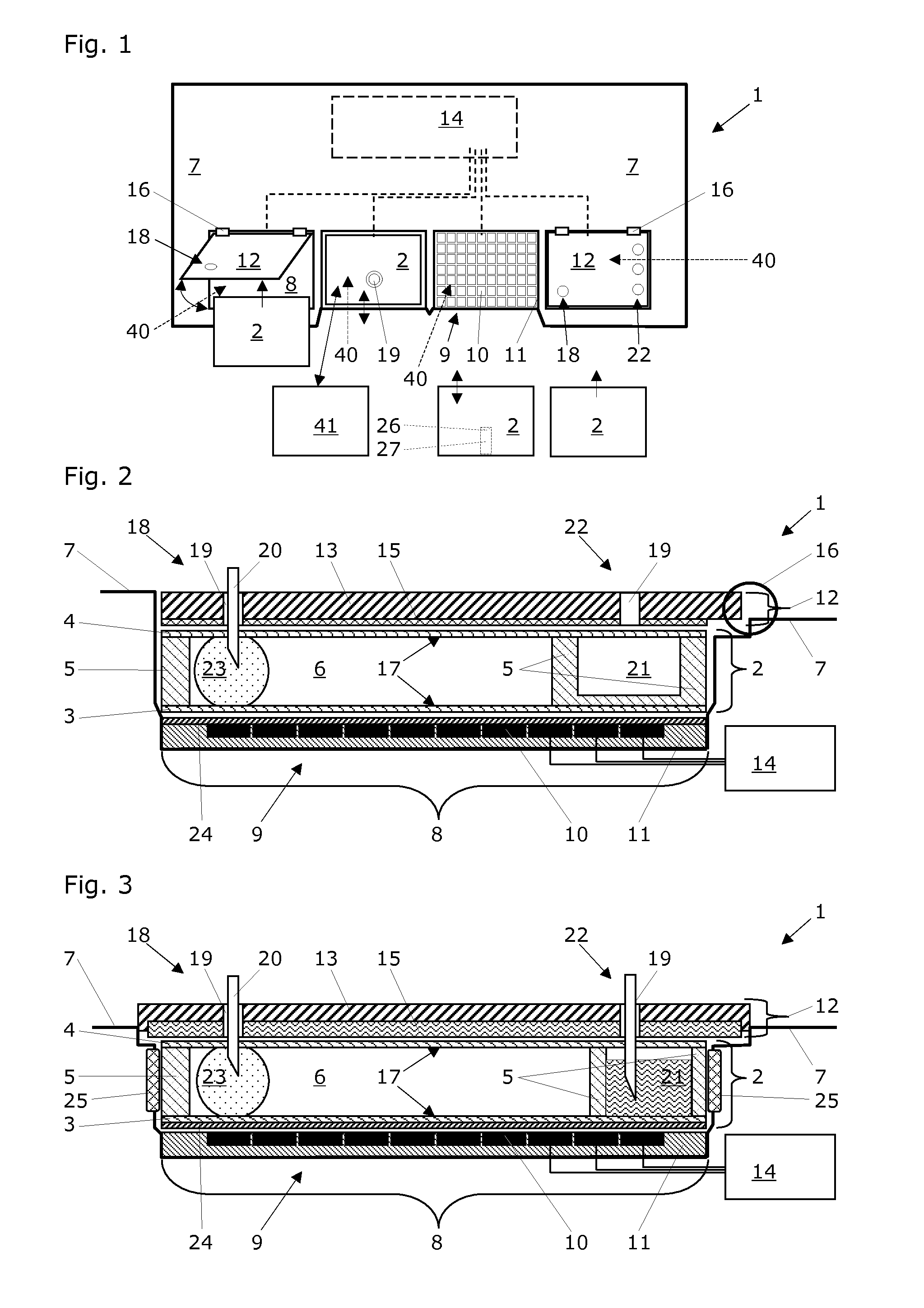
[0080]The FIG. 2 shows a section view of one exemplary cartridge accommodation site 8 with a disposable cartridge 2 accommodated therein. The cover plate 12 is mechanically connected with the base unit 7 of the digital microfluidics system 1 via a hinge 16; thus, the cover plate 12 can swing open and a disposable cartridge 2 can be placed on the cartridge accommodation site 8 via top-entry loading (see FIG. 1). The electrically conductive material 15 of the cover plate 12 is configured as a thin metal plate or metal foil that is attached to the top substrate 13. Alternatively, the electrically conductive material 15 of the cover plate 12 is configured as a metal layer that is deposited onto the top substrate 13. Such deposition of the conductive material 15 may be carried out by chemical or physical vapor deposition techniques as they are known per se.

[0081]The cover plate 12 is configured to apply a force to a disposable cartridge 2 that is accommodated at the cartridge accommodat...

second embodiment

[0083]The FIG. 3 shows a section view of one exemplary cartridge accommodation site 8 with a disposable cartridge 2 accommodated therein. Different to the previous embodiment, the cover plate 12 is mechanically connected with the base unit 7 of the digital microfluidics system 1 and immovably fixed therewith. The electrically conductive material 15 of the cover plate 12 is configured as a thick metal plate that is attached to the top substrate 13. Here, the cover plate 12 is not configured to apply a force to the disposable cartridge 2 that is accommodated at the cartridge accommodation site 8 of the base unit 7; thus, the cover plate 12 stays in place and a disposable cartridge 2 can be placed on the cartridge accommodation site 8 via front-entry loading. Such front-entry loading usually includes a movement of the disposable cartridge 2 in a direction that is parallel to the electrode array 9 (see FIG. 1). In order to enable proper drawing-in of the disposable cartridge 2 and to n...

sixth embodiment

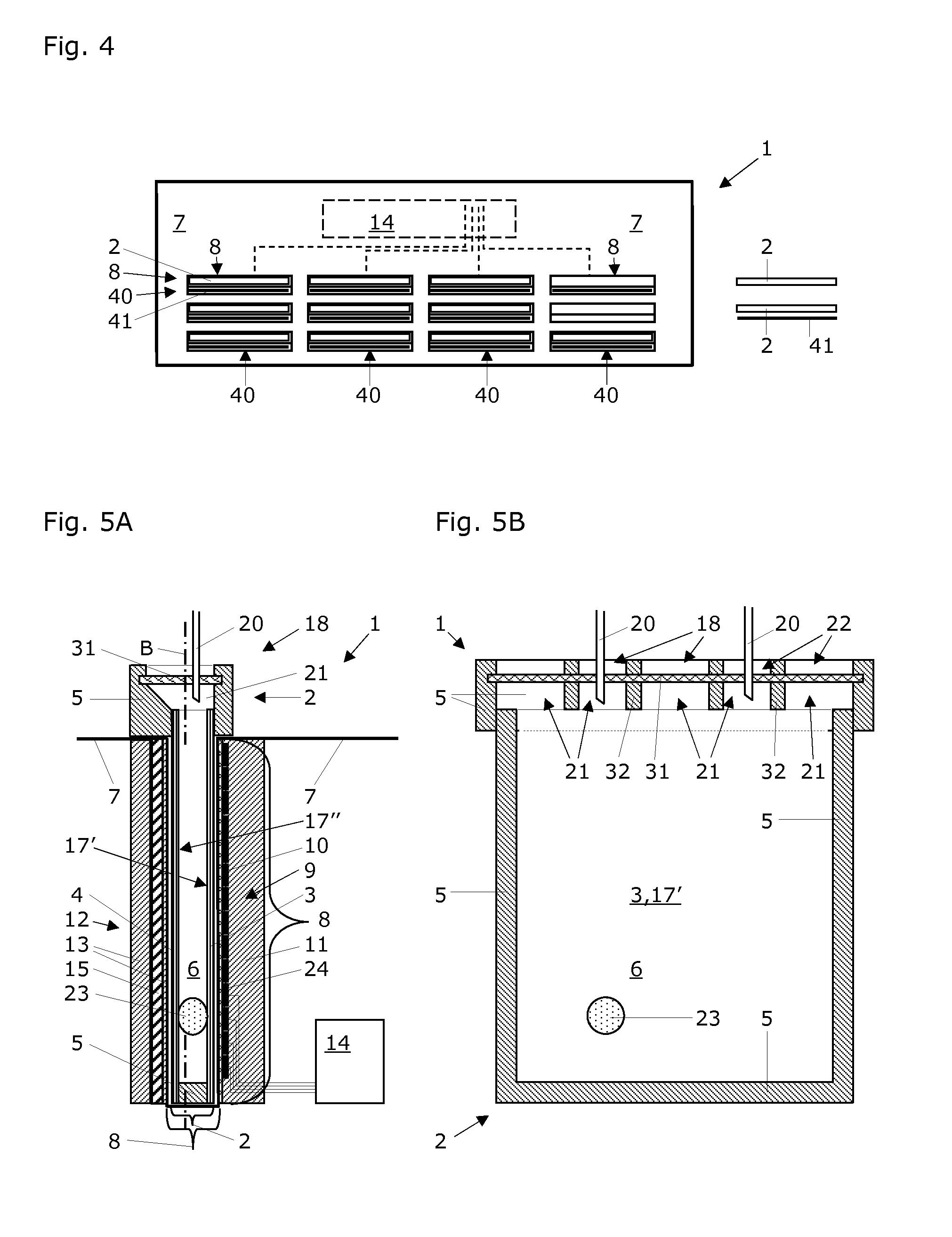
[0089]The FIG. 4 shows an overview over a digital microfluidics system 1 that is equipped with a central control unit 14 and a base unit 7, with twelve cartridge accommodation sites 8 that each may comprise a fixed cover plate 12. This base unit 7 is particularly suited for taking up cartridges 2 and loading these cartridges into substantially vertical cartridge accommodation sites 8 with a substantially vertical electrode array 9 and cover plate 12 (see FIG. 5). Such loading preferably is carried out by a robotized gripping device of a liquid handling workstation (not shown).

[0090]According to the present invention, this digital microfluidics system 1 also comprises twelve board accommodation sites 40 for receiving a swappable electrode board 41 that each comprises an electrode array 9. In this exemplary embodiment of FIG. 4, all cartridge accommodation sites 8 and board accommodation sites 40 are grouped in pairs, the board accommodation sites 40 being located immediately below t...


PUM

PropertyMeasurementUnit
sizeaaaaaaaaaa
gap widthaaaaaaaaaa
voltageaaaaaaaaaa

Abstract

Digital microfluidics system manipulates samples in liquid droplets within disposable cartridges that have bottom layer, top layer, and gap between the bottom and top layers. The system has a base unit with cartridge accommodation sites and a central control unit for controlling selection of individual electrodes of electrode arrays and for providing these electrodes with individual voltage pulses for manipulating liquid droplets within the cartridges by electrowetting. The system further has board accommodation sites located at the cartridge accommodation sites that each can take up a swappable electrode board having an electrode array and electrical board contact elements individually connected to electrodes of the electrode array. Each board accommodation site has electrical base unit contact elements that are connected to the central control unit and that are configured to engage with the electrical board contact elements of a swappable electrode board that is placed at the board accommodation site.

Description

RELATED PATENT APPLICATIONS[0001]This patent application is a Continuation In Part application to the U.S. patent application Ser. No. 13 / 304,481 filed on Nov. 25, 2011, the disclosure of which being herein incorporated in its entirety.FIELD OF TECHNOLOGY[0002]The present invention relates to a digital microfluidics system or device into which one or more disposable cartridges for manipulating samples in liquid droplets therein can be inserted. The digital microfluidics system comprises an electrode array supported by a substrate, and a central control unit for controlling the selection of individual electrodes of this electrode array and for providing them with individual voltage pulses for manipulating liquid droplets by electrowetting. Thus, the invention also relates to droplet actuator devices for facilitating droplet actuated molecular techniques. This technical field generally relates to the control and manipulation of liquids in a small volume, usually in the micro- or nanos...

Claims


Application Information

Patent Timeline
Patent Type & Authority Applications(United States)
IPC IPC(8): G01N27/447
CPCG01N27/44743G01N27/44791B01L3/502715B01L3/502792B01L3/505B01L2200/027B01L2200/0673B01L2300/043B01L2300/044B01L2300/089B01L2300/123B01L2400/0427B01L2200/04
Inventor FEIGLIN, MARC N.
Owner TECAN TRADING AG
Why Eureka
Try Eureka