Laser beam welding

a laser beam and welding technology, applied in welding/soldering/cutting articles, metal working equipment, manufacturing tools, etc., can solve the problems of nitrogen gas bubbles trapped in the weld, porous welds formed between components that have undergone certain types of surface treatment,

Active Publication Date: 2013-10-17
MAGNA INTERNATIONAL INC
View PDF5 Cites 26 Cited by
  • Summary
  • Abstract
  • Description
  • Claims
  • Application Information

AI Technical Summary

Benefits of technology

[0007]According to an aspect of at least one embodiment of the instant invention, a process is disclosed for the joining together of two or more components by laser beam welding. The disclosed process at least partially overcomes some of the disadvantages that are associated with the prior art processes. For instance, laser beam welds that are formed between components that have undergone certain types of surface treatments are known to be porous and of generally unacceptable quality. This porosity of the laser beam weld is attributed to the decomposition of the nitride layer within the joint between the components at elevated—but below welding—temperatures, which leads to bubbles of nitrogen gas becoming trapped in the weld. The process that is disclosed in this document uses a filler wire with a core that contains a specially formulated metallic composite, including an

Problems solved by technology

For instance, laser beam welds that are formed between components that have undergone certain types of surface treatments are known to be porous and of generally unacceptable quality.
This porosity of the laser beam

Method used


Image

  • Laser beam welding
  • Laser beam welding
  • Laser beam welding

Examples


Embodiment Construction

[0019]The following description is presented to enable a person skilled in the art to make and use the invention, and is provided in the context of a particular application and its requirements. Various modifications to the disclosed embodiments will be readily apparent to those skilled in the art, and the general principles defined herein may be applied to other embodiments and applications without departing from the scope of the invention. Thus, the present invention is not intended to be limited to the embodiments disclosed, but is to be accorded the widest scope consistent with the principles and features disclosed herein.

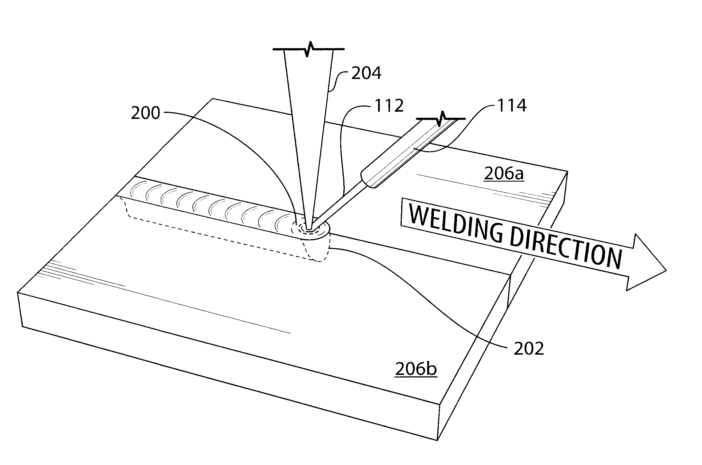
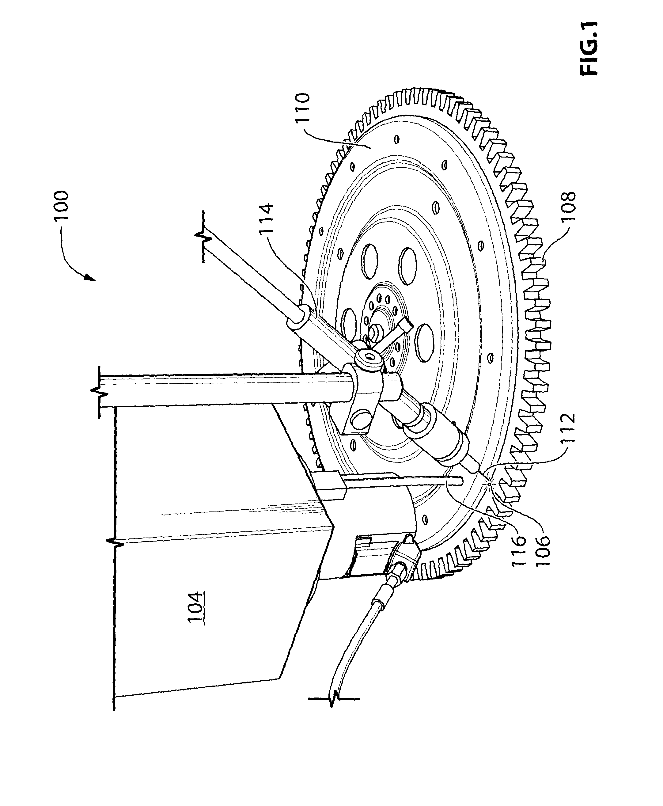
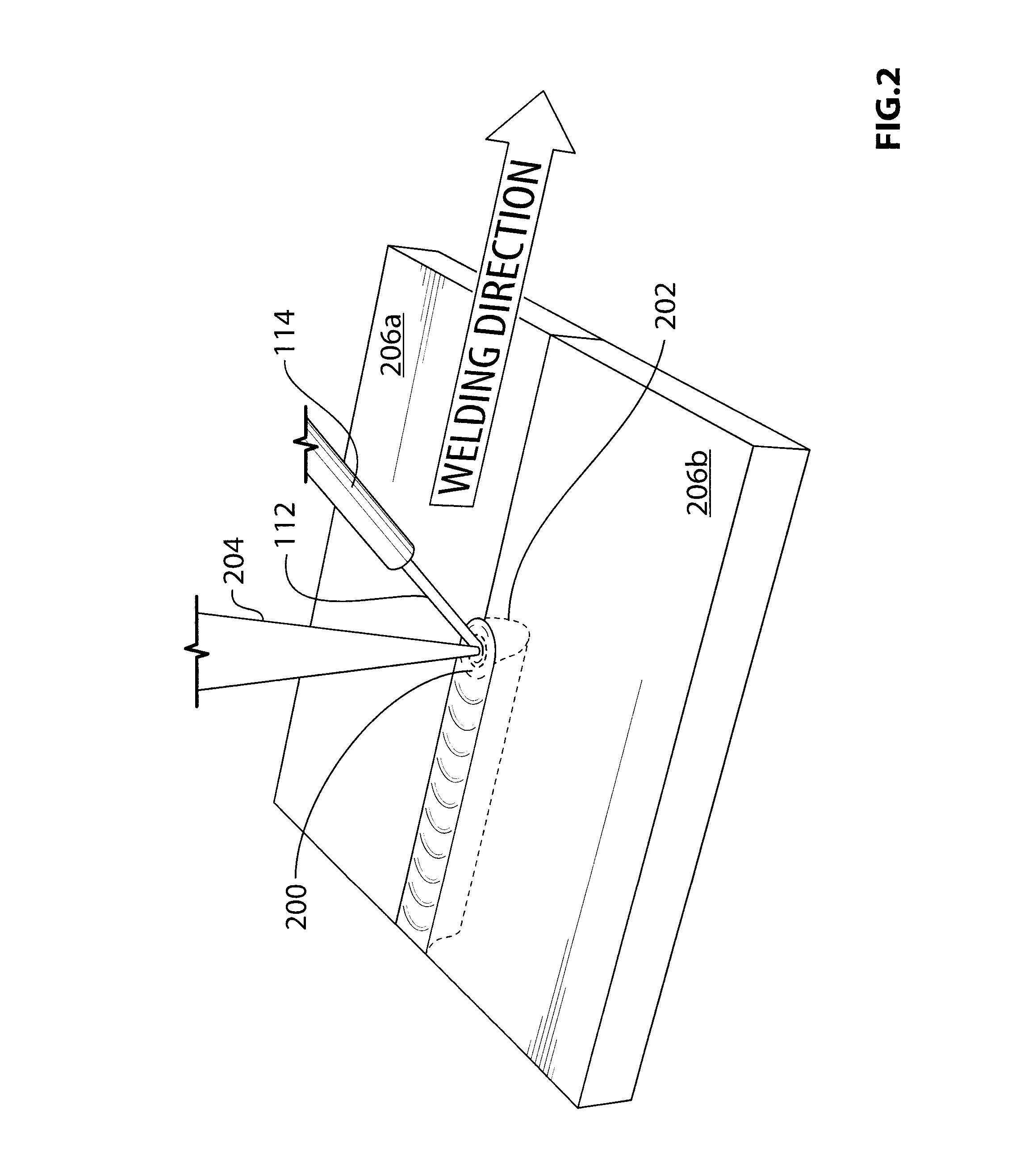
[0020]Referring to FIG. 1, shown is a simplified perspective view of a laser welding system, which is suitable for implementing a process according to an embodiment of the instant invention. In particular, the system of FIG. 1 is suitable for laser welding nitride steel components as well as other types of surface treated metal components. The system that is sh...


PUM

PropertyMeasurementUnit
Temperatureaaaaaaaaaa
Metallic bondaaaaaaaaaa

Abstract

A process is provided for laser beam welding of surface treated steel components. Two steel components, at least one of which is a surface treated steel component, are relatively arranged to form a joint that is to be welded. Using a laser beam, the two steel components are irradiated along the joint so as to heat materials within each of the two steel components to a welding temperature, and thereby form a weld pool. During welding a metallic constituent is introduced into a leading edge of the weld pool, in front of the laser beam along a welding direction. The introduced metallic constituent combines with a species, which is released into the weld pool from the surface treated steel component, to form a compound that is stable within the weld pool at the welding temperature.

Description

[0001]This application claims the benefit under 35 U.S.C. 119(e) of U.S. Provisional Patent Application No. 61 / 424,327, which was filed on Dec. 17, 2010, the entire contents of which are incorporated herein by reference.FIELD OF THE INVENTION[0002]The instant invention relates generally to laser beam welding, and more particularly to laser beam welding of surface treated metal components, such as for instance nitride steels, using a metal-cored filler wire containing alloying constituents.BACKGROUND OF THE INVENTION[0003]Laser beam welding is a joining technique that offers a number of advantages over conventional gas metal arc welding (GMAW), such as for instance low heat input, short cycle time and good cosmetic welds. The process is frequently used in high volume applications, such as for instance the welding together of powertrain components in the automotive industry. In this way, components that contain multiple grades or multiple types of material can be manufactured at relat...

Claims


Application Information

Patent Timeline
IPC IPC(8): B23K26/20
CPCB23K26/203B23K26/28B23K26/211B23K2101/35B23K2103/08B23K2103/50B23K26/32B23K26/20B23K31/00B23K26/322
Inventor GU, HONGPINGYIN, GUOBINSHULKIN, BORIS
Owner MAGNA INTERNATIONAL INC
Why Eureka
Try Eureka