
Wind turbine with improved cooling

a technology of wind turbines and cooling coils, applied in the direction of electric generator control, machine/engine, magnetic circuit shape/form/construction, etc., can solve the problems of reducing the effectiveness of wind turbines and their operating time, affecting the efficiency of wind turbines, and affecting the cooling effect of stator coils, etc., to achieve the effect of effective cooling of stator coils

Inactive Publication Date: 2013-10-17
ENVISION ENERGY DENMARK
View PDF9 Cites 23 Cited by
  • Summary
  • Abstract
  • Description
  • Claims
  • Application Information

AI Technical Summary

Benefits of technology

This patent aims to provide improvements for cooling the stator coils during operation of generators. The main technical effects include reducing weight and power output limitations, as well as improving coolant flow and reducing temperature rise along the flow direction.

Problems solved by technology

A known problem with these conventional generators is that the windings are subjected to temperature cycling when the load on the wind turbine changes, causing repeating thermal stress on the windings, clamping structure, seals and gasket, which causes the generator to fail.
Without cooling the components, e.g. the windings, inside the generator will loose its conducting capability due to the temperature rise which in turn reduces the effectiveness of the wind turbine and its operating time.
The cooling flow is looped axially from one cooling channel to another cooling channel via an interconnecting pipe section; this axial loop causes the temperature to rise unacceptably along the flow direction and reduces the effect of the cooling.
This reduces the effect of the cooling as the temperature in the reservoir increases, since heat generated in the generator is not circulated outside the generator housing.
The separated stator teeth do not provide an effective heat transfer path from the stator coils to the annulus.
Furthermore, this configuration is not able to generate a sufficient pressure in the coolant, since the coolant is lead directly from one chamber to the other chamber via the cooling channel and the annulus.

Method used


Image

  • Wind turbine with improved cooling
  • Wind turbine with improved cooling
  • Wind turbine with improved cooling

Examples


Embodiment Construction

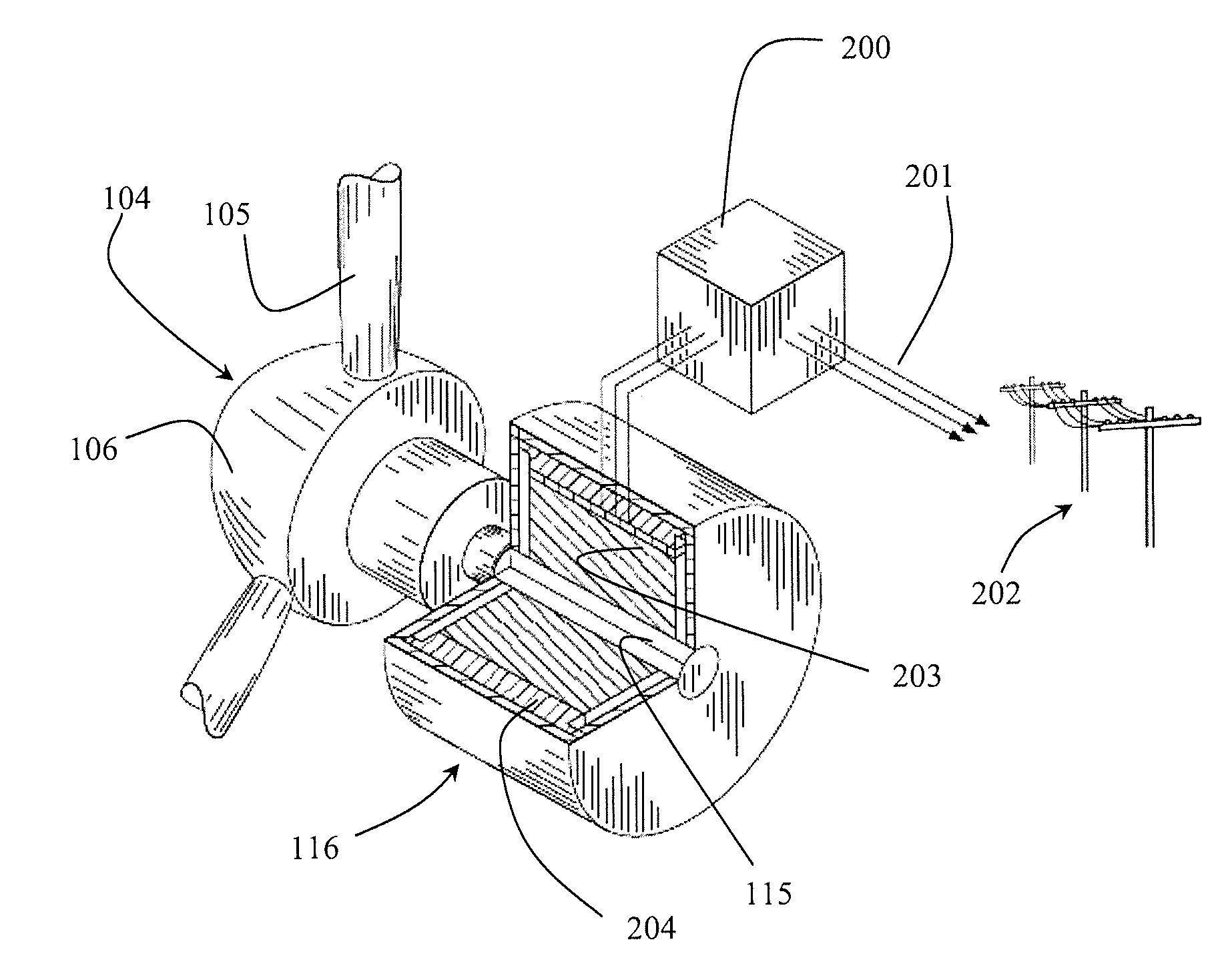
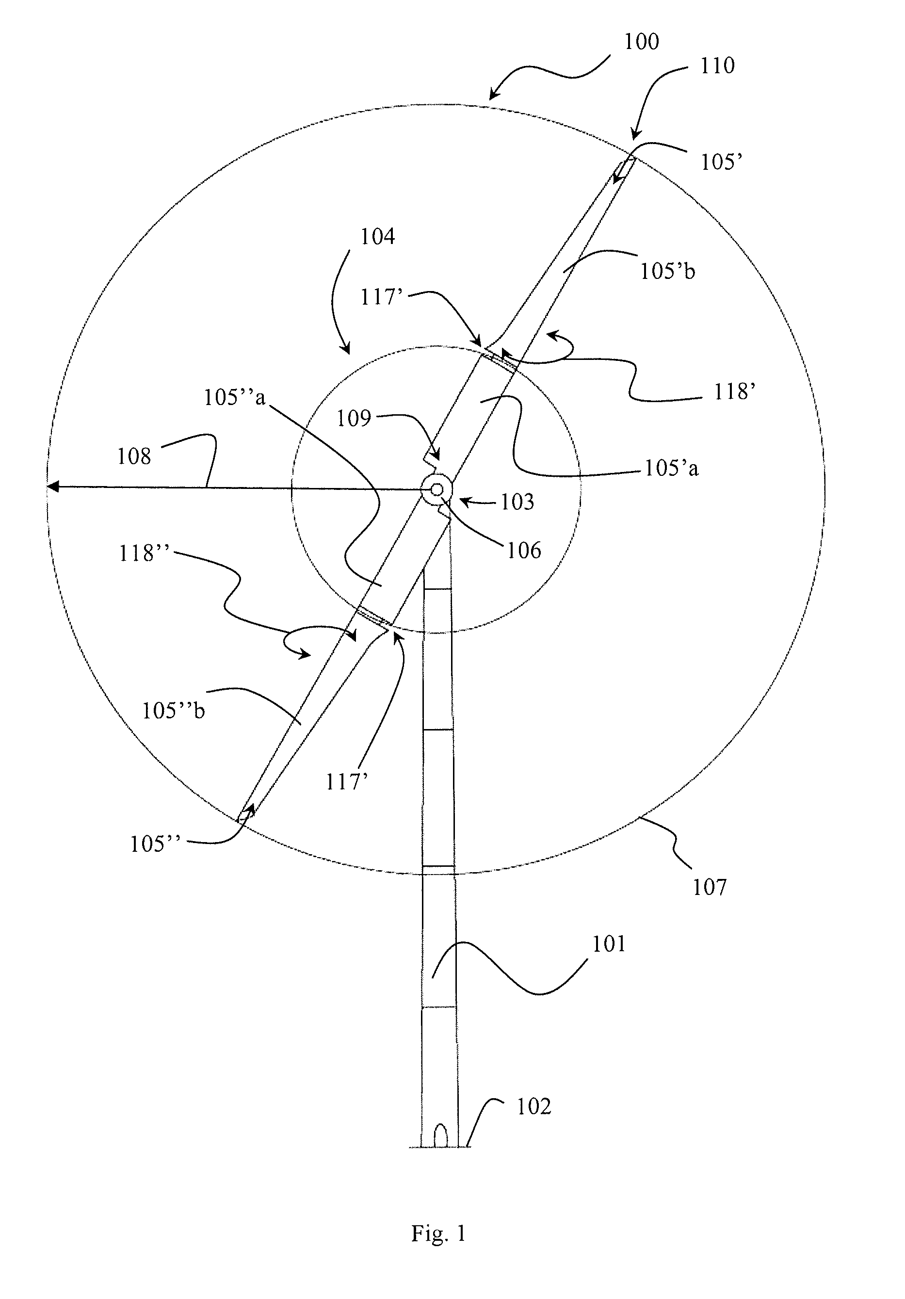
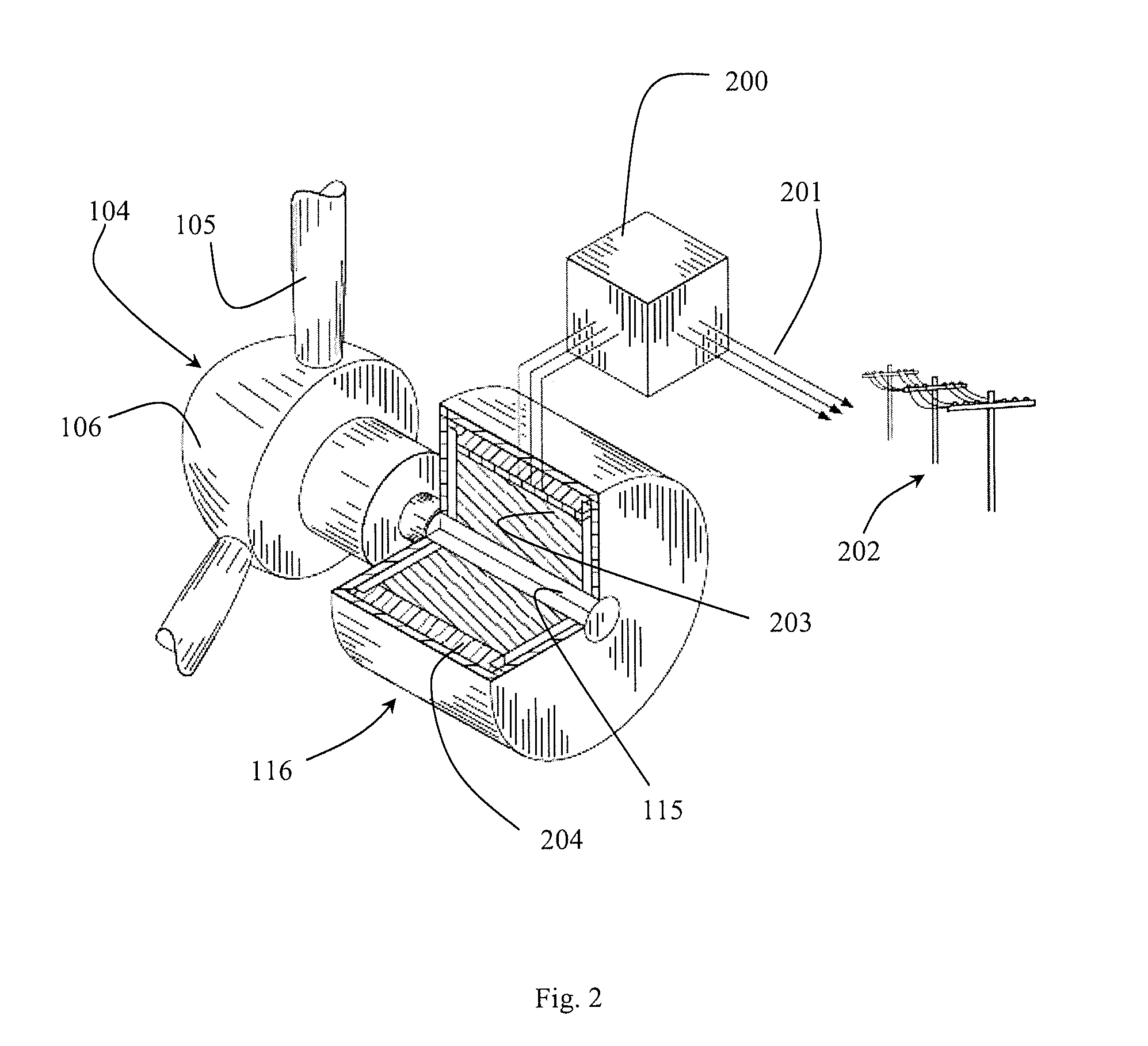
[0019]An object of the invention is achieved by a wind turbine comprising:[0020]a wind turbine tower;[0021]a nacelle provided on the wind turbine;[0022]a wind turbine rotor hub rotatably mounted at the nacelle, the wind turbine rotor hub having one or more wind turbine blades mounted thereon;[0023]a shaft coupled to the wind turbine rotor hub,[0024]a generator coupled to the shaft and which comprises a rotor arranged rotably in relation to a stator, wherein the rotor comprises one or more superconducting rotor coils, wherein the stator comprising one or more stator coils of a conductive material, and wherein the rotor coil and the stator coil being arranged to have interacting magnetic fields for inducing a current in the stator coil when the rotor is rotated, and[0025]wherein the stator coils are arranged in a stator chamber inside a stator housing in which the stator iron separates the stator chamber into a first chamber and a second chamber, wherein the stator iron and at least a...


PUM


Abstract

A wind turbine with a wind turbine tower; a nacelle; a wind turbine rotor hub having at least one blade mounted thereon; a shaft coupled to the wind turbine rotor hub, and to a generator which has a rotor with at least one superconducting rotor coil and a stator with at least one conductive stator coil. The rotor coil and the stator coil have interacting magnetic fields for inducing current in the stator coil. A stator iron and at least a part of the stator coils are thermally coupled by first and second types of cooling channels along an inner and an outer periphery of the stator iron, respectively. The cooling channels guide a coolant that conducts heat away from the stator coil. Interconnecting pipes are coupled to at least a first chamber or a second chamber of the second type of cooling channels.

Description

BACKGROUND OF THE INVENTION[0001]1. Field of the Invention[0002]The present invention relates to a wind turbine comprising:[0003]a wind turbine tower;[0004]a nacelle provided on the wind turbine;[0005]a wind turbine rotor hub rotatably mounted at the nacelle, the wind turbine rotor hub having one or more wind turbine blades mounted thereon;[0006]a shaft coupled to the wind turbine rotor hub, and[0007]a generator coupled to the shaft and which comprises a rotor arranged rotably in relation to a stator, wherein the rotor comprises one or more superconducting rotor coils, wherein the stator comprising one or more stator coils of a conductive material, and wherein the rotor coil and the stator coil being arranged to have interacting magnetic fields for inducing a current in the stator coil when the rotor is rotated.[0008]2. Description of Related Art[0009]During recent developments superconducting generators have been used for wind turbines. Superconductors are typically lighter and sma...

Claims


Application Information

Patent Timeline
IPC IPC(8): H02K9/19H02K9/00F03D9/00
CPCH02K9/19F03D9/002H02K9/005H02K1/20H02K7/1838H02K9/197F03D9/25Y02E10/72F03D9/255F03D80/60
Inventor RASMUSSEN, PETER
Owner ENVISION ENERGY DENMARK
Learn More