Switching power supply apparatus

a power supply and power supply technology, applied in the direction of electric variable regulation, process and machine control, instruments, etc., can solve the problem of large electrical power loss, and achieve the effect of reducing electrical power loss

Active Publication Date: 2013-10-17
MURATA MFG CO LTD
View PDF8 Cites 11 Cited by
  • Summary
  • Abstract
  • Description
  • Claims
  • Application Information

AI Technical Summary

Benefits of technology

[0015]According to various preferred embodiments of the present invention, a surge voltage is suppressed while electrical power loss is reduced by accumulating charge in, and then discharging the charge from, a first capacitor.

Problems solved by technology

However, in this example of the background art, there is a problem in that energy absorbed by the capacitor in order to suppress the surge voltage is accumulated as charge and then consumed by the resistor and therefore electrical power loss is large.

Method used


Image

  • Switching power supply apparatus
  • Switching power supply apparatus
  • Switching power supply apparatus

Examples


Embodiment Construction

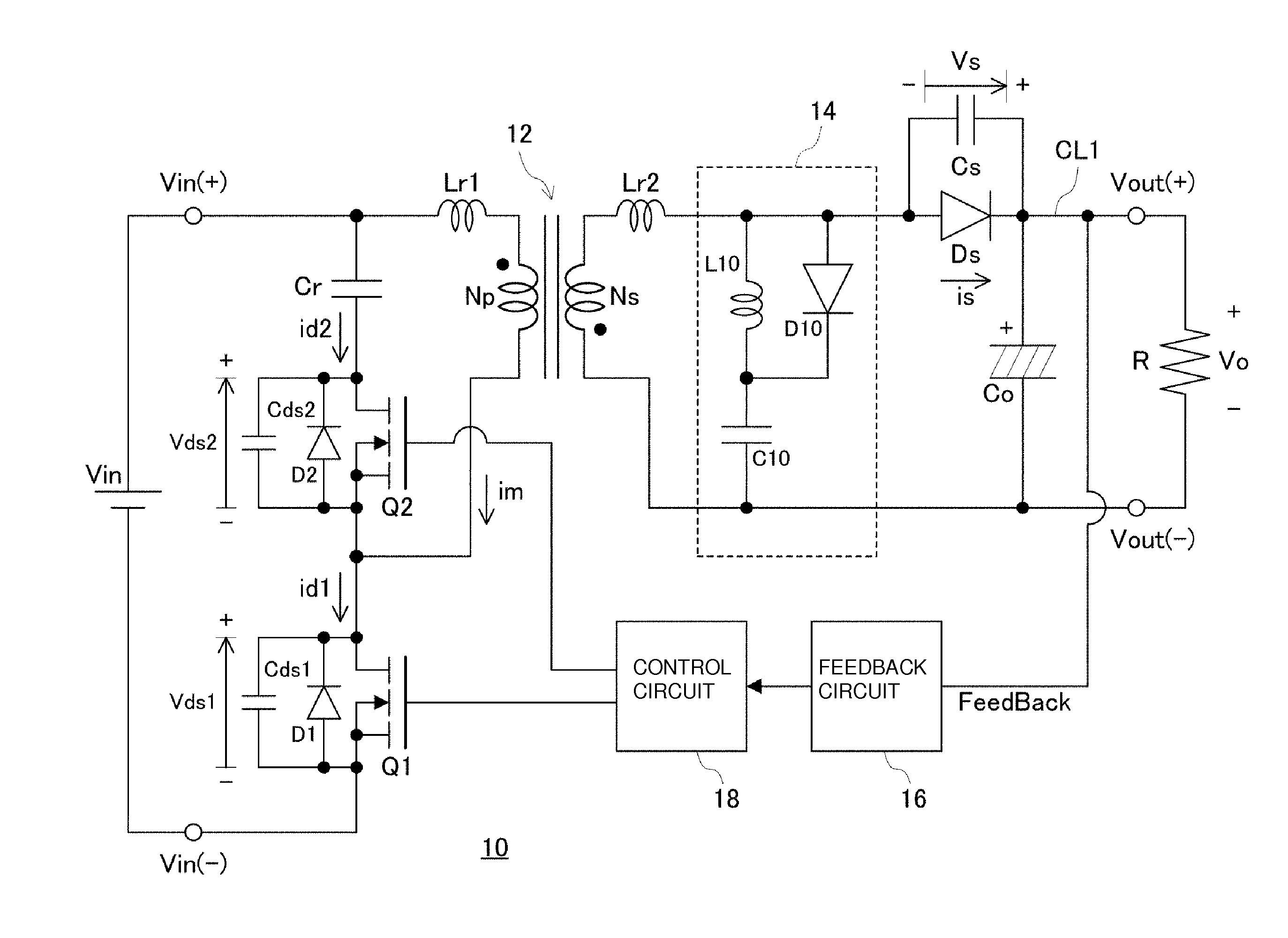
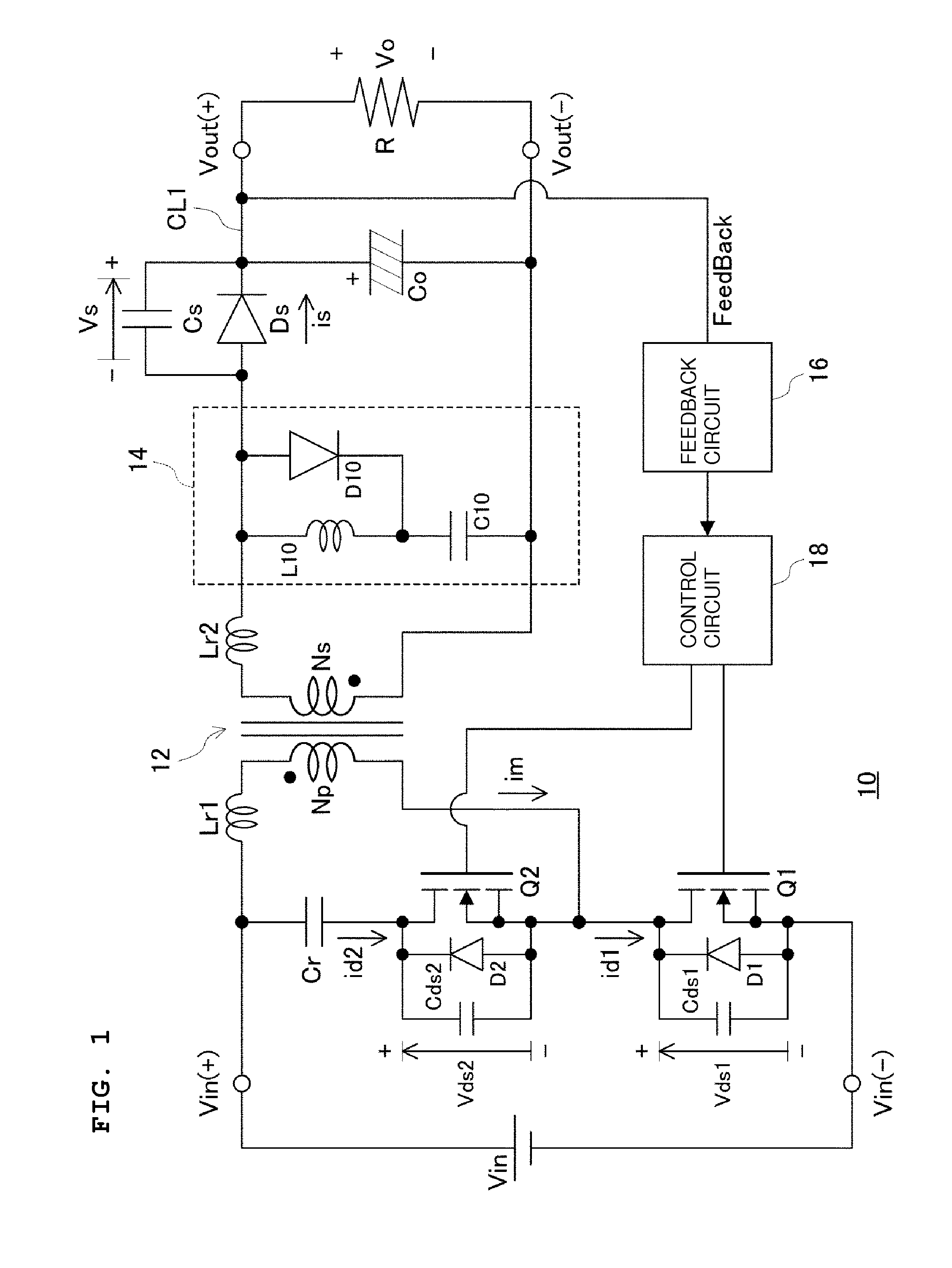
[0024]Preferred embodiments of the present invention will now be discussed with reference to the accompanying drawings. Referring to FIG. 1, a switching power supply apparatus 10 of a preferred embodiment of the present invention includes a transformer 12 including a primary winding Np and a secondary winding Ns, which are magnetically coupled with each other. One end of the primary winding Np is connected to a positive terminal Vin(+) of a direct current power supply Vin and the other end of the primary winding Np is connected to a negative terminal Vin(−) of the direct current power supply Vin via a switching element Q1. More specifically, the switching element Q1 preferably is a Field Effect Transistor (FET) and the other end of the primary winding Np is connected to the drain of the switching element Q1 and the negative terminal Vin(−) of the direct current power supply Vin is connected to the source of the switching element Q1.

[0025]A capacitor Cr and a switching element Q2, wh...


PUM


Abstract

A transformer that realizes ZVS operation includes a primary winding and a secondary winding. A control circuit turns switching elements on and off in a complimentary manner in order to repeatedly invert the voltage applied to the primary winding. A conduction path supplies a voltage excited in the secondary winding to a load connected between a high-potential side and a ground side of the secondary winding. A first rectifier diode has a rectification direction extending from the high-potential side toward the ground side of the load and is provided along the conduction path. A second rectifier diode and a capacitor, which are connected in series with each other, are connected in parallel with the secondary winding. An inductor is connected in parallel with the second rectifier diode. A rectification direction of the second rectifier diode matches the direction extending from the high-potential side to the ground side.

Description

BACKGROUND OF THE INVENTION[0001]1. Field of the Invention[0002]The present invention relates to switching power supply apparatuses and, in particular, relates to switching power supply apparatuses that repeatedly invert a voltage applied to a primary side of a transformer by using switching elements and supply a voltage excited in a secondary side of the transformer to a load via a rectifier diode.[0003]2. Description of the Related Art[0004]An example of a conventional switching power supply apparatus is disclosed in Japanese Unexamined Patent Application Publication No. 8-51777. In Japanese Unexamined Patent Application Publication No. 8-51777, a diode and a capacitor, which are connected in series with each other, are connected in parallel with a feedback winding of a transformer and a resistor is connected in parallel with the capacitor. Here, the cathode of the diode is connected to one end of the feedback winding and the anode of the diode is connected to the capacitor. The t...

Claims


Application Information

Patent Timeline
Patent Type & Authority Applications(United States)
IPC IPC(8): H02M3/335
CPCH02M3/33569H02M1/34Y02B70/10H02M1/346H02M3/33573H02M3/33571H02M3/01
Inventor HOSOTANI, TATSUYA
Owner MURATA MFG CO LTD
Why Eureka
Try Eureka