Fiber optic cantilever acoustic vector sensor

a technology of acoustic vector and fiber optics, which is applied in the field of fiber optic laser sensors, can solve the problems of achieving high acoustic sensitivity over a large bandwidth from a small sensor, and achieve the effects of excellent long-term reliability, high sensitivity to axial strain, and low weigh

Inactive Publication Date: 2013-10-17
THE UNITED STATES OF AMERICA AS REPRESENTED BY THE SECRETARY OF THE NAVY
View PDF1 Cites 12 Cited by
  • Summary
  • Abstract
  • Description
  • Claims
  • Application Information

AI Technical Summary

Benefits of technology

[0027]The deflections of the cantilever are measured with a fiber laser sensor. This fiber optic sensor provides very high sensitivity to axial strain induced in the core through flexure of the optical fiber, necessary for acoustic measurements. Along with the established benefits of fiber optic sensors for undersea acoustic measurements such as excellent long term reliability, low weight and immunity to electromagnetic interference, an acoustic vector sensor based on the present concept has a many other favorable attributes (a) it can be made very small and lightweight since the fiber constitutes both the mechanical oscillator and the sensor, (b) a single multicore fiber can potentially measure two vector components of the acoustic field, and (c) a smooth response to particle velocity can be achieved due to significant viscous fluid damping arising from low Reynolds number flow around a small cantilever.

Problems solved by technology

However, achieving high acoustic sensitivity over a large bandwidth from a small sensor remains a challenge.

Method used


Image

  • Fiber optic cantilever acoustic vector sensor
  • Fiber optic cantilever acoustic vector sensor
  • Fiber optic cantilever acoustic vector sensor

Examples


Embodiment Construction

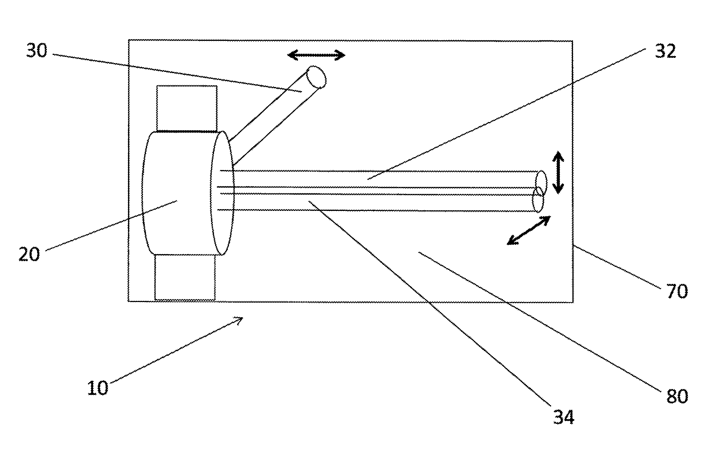
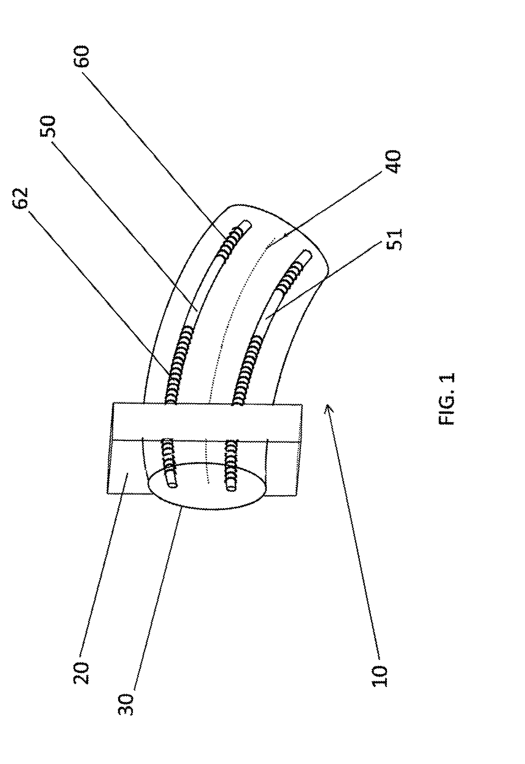
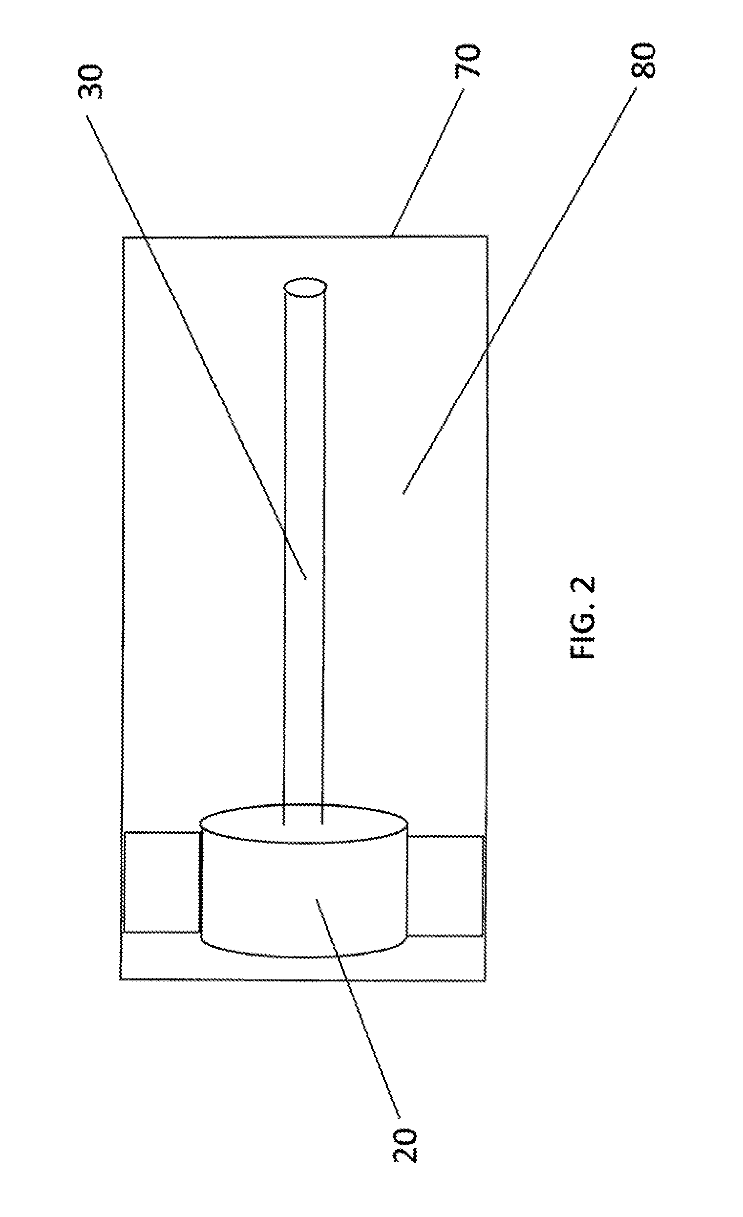
[0037]As shown by way of illustration in FIGS. 1-5 and 6A-C, an embodiment of the invention includes a cylindrical, cantilever-type apparatus 10 including a rigid support 20. The cylindrical, cantilever-type apparatus 10 further includes a first optical fiber 30 connected to the rigid support 20, the first optical fiber including a first neutral axis 40 and at least one first wave-guiding core 50 running parallel to the first neutral axis and located at a distance from the first neutral axis, each of the at least one first wave-guiding core 50 including at least one first reflector 60, 62. The cylindrical, cantilever-type apparatus 10 further includes a first membrane 70 surrounding the first optical fiber 30; and a first liquid 80 inside the first membrane 70 and surrounding the first optical fiber 30, the first liquid including a Reynolds number less than one.

[0038]For example, the first optical fiber 30 is embedded in the rigid support 20, as shown by way of illustration in FIG. ...


PUM


Abstract

A planar or cylindrical, cantilever-type apparatus including a rigid support. The apparatus further includes a first optical fiber connected to the rigid support, the first optical fiber including a first neutral axis and at least one first wave-guiding core running parallel to the first neutral axis and located at a distance from the first neutral axis, each of the at least one first wave-guiding core including at least one first reflector. The apparatus further includes a first membrane surrounding the first optical fiber; and a first liquid inside the first membrane and surrounding the first optical fiber, the first liquid including a Reynolds number less than one.

Description

CROSS REFERENCE TO RELATED APPLICATIONS[0001]The present application claims priority U.S. Provisional Patent Application Ser. No. 61 / 624,55 filed 16 Apr. 2012.FIELD OF THE INVENTION[0002]The invention relates generally to fiber optic laser sensors, and more particularly to fiber optic acoustic vector sensors.BACKGROUND OF THE INVENTION[0003]The benefits of characterizing an acoustic field by measuring particle motion, instead of local changes in ambient a pressure, have long been known. Measurement of the particle motion in terms of displacement, velocity or acceleration reveal information on the field direction as well as amplitude. Simultaneous measurement of the local pressure, p, and particle velocity, {dot over (u)}, in a plane wave also yields the acoustic intensity through the relationship, I=<real(p)real({dot over (u)})>T, where <>T denotes time average. Here, u, is particle displacement and {dot over (u)} denotes differentiation with respect to time. When it is ...

Claims


Application Information

Patent Timeline
Patent Type & Authority Applications(United States)
IPC IPC(8): G02B6/34
CPCG02B6/34G01L11/025G02B6/022G01D5/35316G01H9/004G01D5/3537G01K11/3206G01L1/242G02B6/02076
Inventor CRANCH, GEOFFREY A.KIRKENDALL, CLAY K.
Owner THE UNITED STATES OF AMERICA AS REPRESENTED BY THE SECRETARY OF THE NAVY
Why Eureka
Try Eureka