Supercharge Your Innovation With Domain-Expert AI Agents!

Radio frequency signal receiving device

a technology of receiving device and frequency signal, which is applied in the direction of low noise amplifier, transmission, amplifier modification to reduce noise influence, etc., to achieve the effect of reducing power consumption, suitable frequency response, and effectively reducing flicker nois

Active Publication Date: 2013-10-17
SINO WEALTH ELECTRONICS
View PDF11 Cites 2 Cited by
  • Summary
  • Abstract
  • Description
  • Claims
  • Application Information

AI Technical Summary

Benefits of technology

This patent describes a device that reduces power consumption and improves the frequency response of a radio signal receiving device. It achieves this by connecting two inductors in series between the output ends of the device's main component, the LNA. The inductors create a resonance effect that reduces flicker noises and improves the quality of the received signal. This results in a more reliable and efficient device for RF signal receiving.

Problems solved by technology

Therefore, in consideration of the broadband performance, designers may face more challenges, which include how to design an LNA with broadband input matching, gain bandwidth, and low power consumption.

Method used


Image

  • Radio frequency signal receiving device
  • Radio frequency signal receiving device
  • Radio frequency signal receiving device

Examples


Embodiment Construction

[0061]Examples of embodiments are described in the accompanying drawings with reference to the embodiments of the present invention in detail. In addition, in possible positions, components / members with the same numerals are used in the drawings and embodiments to represent the same or similar parts.

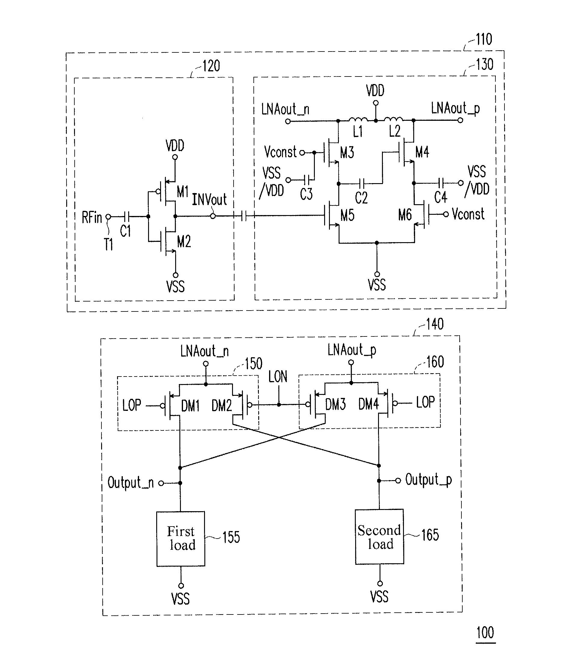
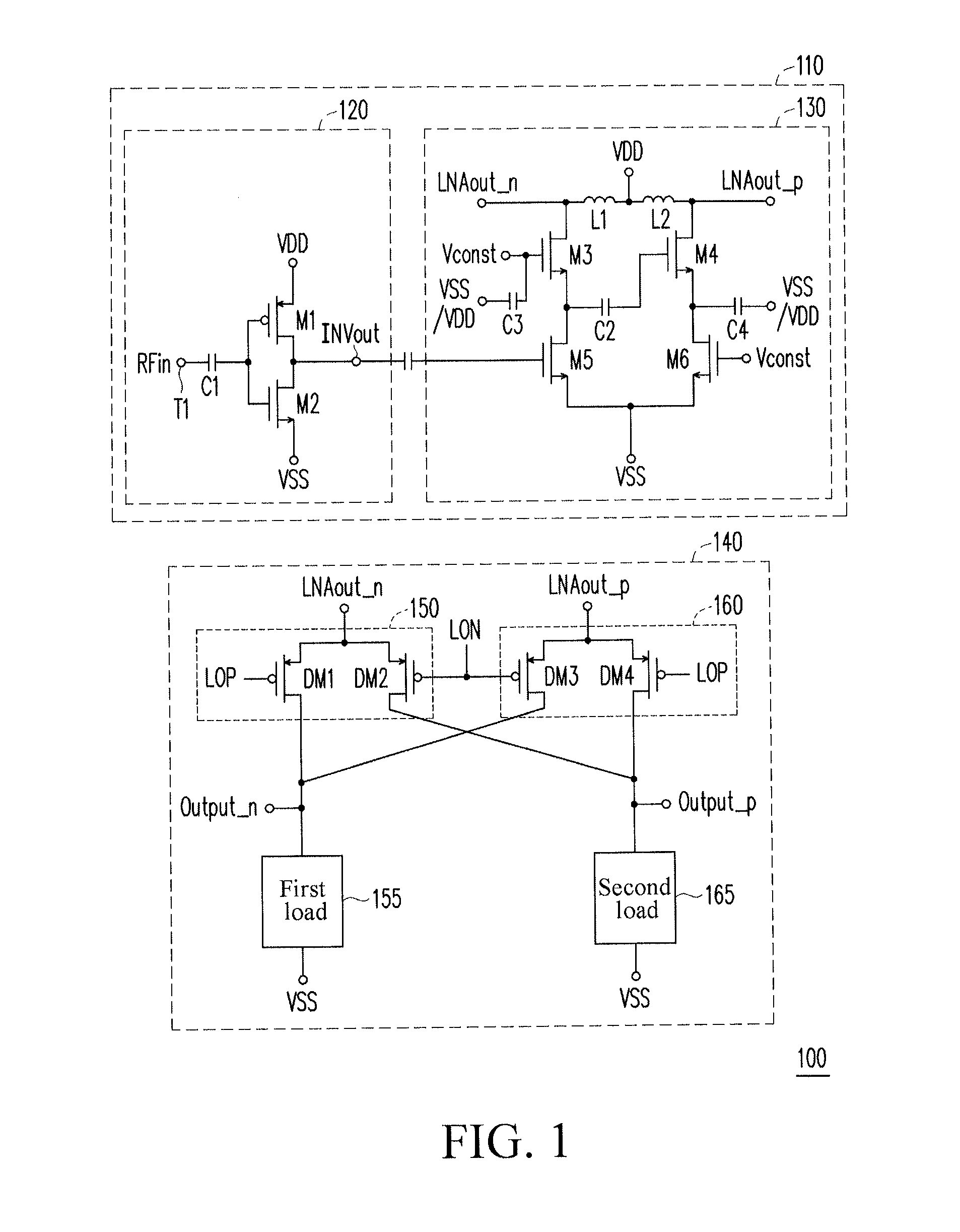
[0062]FIG. 1 is a circuit diagram of a radio frequency signal receiving device according to an embodiment of the present invention. Referring to FIG. 1, the radio frequency signal receiving device 100 includes an LNA 110 and a mixer 140. The LNA 110 has a single input end T1, a first differential output end LNAout_n, and a second differential output end LNAout_p. Further, the LNA 110 has the single input end T1 for receiving a radio frequency input signal RFin, and the LNA 110 includes a first inductor L1 and a second inductor L2. The first inductor L1 is serially connected between the first differential output end LNAout_n and an operating voltage receiving end VDD. The second inductor ...


PUM


Abstract

Disclosed is a radio frequency signal receiving device, which includes a low-noise amplifier (LNA) and a mixer. The LNA includes a first inductor and a second inductor. The mixer has a first differential pair and a second differential pair, common ends of the first differential pair and the second differential pair are respectively coupled to the first differential output end and the second differential output end. The first inductor and the second inductor are serially connected between the first differential output end and the second differential output end of the LNA, so as to reduce power consumption and reach suitable frequency response. The first inductor and the second inductor generate a resonance effect with parasitic capacitance on the mixer, so as to effectively reduce flicker noises, and improve a working benefit of the radio frequency signal receiving device.

Description

BACKGROUND OF THE PRESENT INVENTION[0001]1. Field of Invention[0002]The present invention relates to a radio frequency signal receiving device.[0003]2. Description of Related Arts[0004]In the field of wired communications and wireless communications, so-called broadband communication technologies are proposed in succession, for example, digital video broadcasting-handheld (DVB-H) (470-890 MHz) and cognitive radio (0.1-10 GHz). A low-noise amplifier (LNA) is configured in a first level circuit of a receiving device, so that characteristics of the LNA may directly affect entire performance of the receiving device. Therefore, in consideration of the broadband performance, designers may face more challenges, which include how to design an LNA with broadband input matching, gain bandwidth, and low power consumption.[0005]A mixer is a second level circuit of the receiving device. In design of the mixer, the designers need to consider the power consumption of the mixer, and the area of the...

Claims


Application Information

Patent Timeline
Patent Type & Authority Applications(United States)
IPC IPC(8): H04B1/10
CPCH04B1/10H03D7/1441H03D7/1458H03D7/1466H03F2200/294H03F3/45H03F1/26
Inventor CHIU, SHIH-MINGLIANG, KENG-CHANG
Owner SINO WEALTH ELECTRONICS
Features
  • R&D
  • Intellectual Property
  • Life Sciences
  • Materials
  • Tech Scout
  • Unparalleled Data Quality
  • Higher Quality Content
  • 60% Fewer Hallucinations
Learn More